
Handle Positioning Apparatus Outside Mould for Pre-Inserted-Handle Bottle Blow Moulding Machine, and Method of Use Thereof

a technology of positioning apparatus and blow moulding machine, which is applied in the field of blow moulding, can solve the problems of high transportation cost, high energy consumption during the manufacturing process, and heavy weight, and achieve the effects of saving time, speeding up production cycle, and saving time for waiting

Inactive Publication Date: 2014-11-27
GUANGZHOU ZHANGLIN PLASTIC PRODS
View PDF1 Cites 14 Cited by
  • Summary
  • Abstract
  • Description
  • Claims
  • Application Information

AI Technical Summary

Benefits of technology

The present invention provides a handle positioning apparatus outside mould for a pre-inserted-handle bottle blow moulding machine. This apparatus can improve product quality and increase production efficiency. It uses two positioning ball plungers and positioning beads to limit the closing positions of the left and right positioning panels, which ensures the correct installation of the handle. Compared to existing apparatus, this invention has advantages such as saving time for placing the handle, increasing production capacity, and simplifying the production equipment cost and space requirement.

Problems solved by technology

Furthermore, PET bottles are gradually substituting traditional glass bottles due to a number of disadvantages existing in glass bottles, for example fragility, heavy weight, high energy consumption during the process of manufacturing and high transportation cost etc.
Since the handle and the bottle body are fixed tightly together, the handle has high resistance against tensional force and therefore is not easy to break off.
However, the manufacturing of this kind of bottle requires high cost of labouring but the production efficiency is low.
Although some but not many bottle blow moulding machines for making pre-inserted-handle bottle are equipped with mechanical arms for placing the handles into the moulds before bottle blow moulding, the use of mechanical arms as such does not result in high production efficiency.
Besides, the cost of producing and installing mechanical arms is high.
However, the handle of this kind of bottle is not good at resisting tensional force, and the bottle itself is also not good at resisting pressure.
Therefore this kind of bottle is not suitable for long distance transportation.
As shown above, the methods of manufacture directly affect product properties, production efficiency and the cost of production equipment.
However, the problem of poor production efficiency has not been solved.
Problems associated with this kind of manually operated machines still exists, for example, high level of manpower input, unstable production quality, low production cost and unsafety etc.
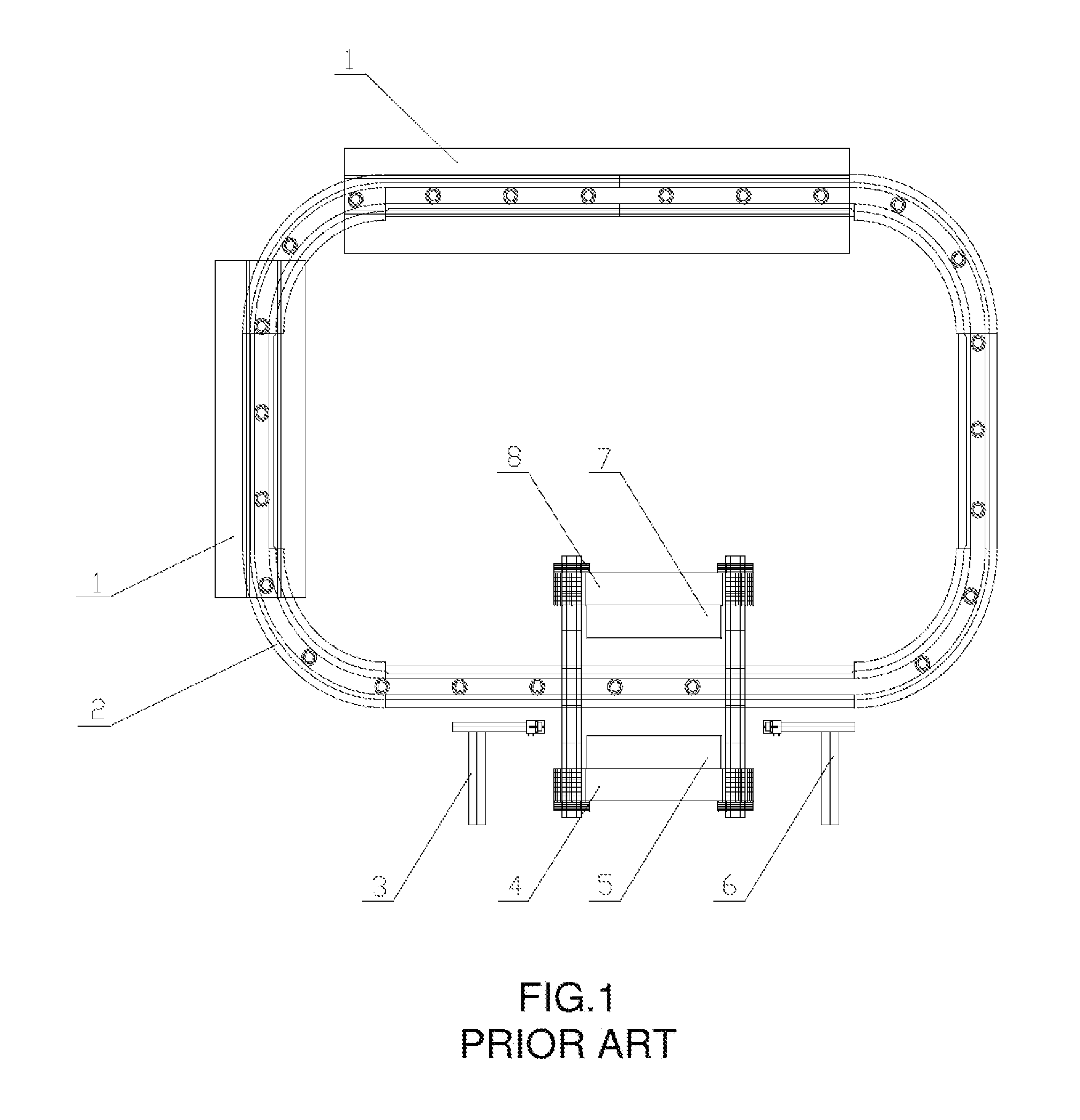
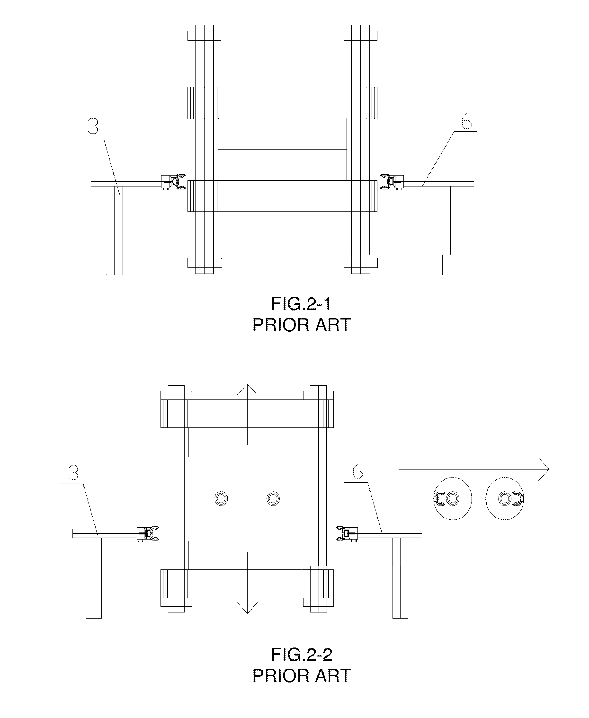
1. Long production cycle and low production efficiency: After blow moulding of a bottle, the bottle must be removed from the mould with a safe distance before the mechanical arms can enter the mould to place another handle therein, and the mould can only close again for blow moulding of the next bottle after the mechanical arms retreat away from the mould with a safe distance. This kind of operation wastes a lot of production time.
2. Maximum production capacity is twin mould production: Constrained by the movement of and the space required by the mechanical arms, the maximum production capacity for each production is limited to twin mould production. Therefore the production efficiency of the bottle blow moulding machine is limited.
3. High production equipment cost: Due to the use of mechanical arms, the equipment itself and its electrical control involve significantly increased cost. Furthermore, the limitation to the production efficiency of the bottle blow moulding machine will result in the need of purchasing a large quantity of this kind of machine in case of voluminous production. As such, the fixed cost of investment into the equipment will be too high compared to its valve, and thus reducing the willingness of investors to invest in this kind of equipment.

Method used


Image

  • Handle Positioning Apparatus Outside Mould for Pre-Inserted-Handle Bottle Blow Moulding Machine, and Method of Use Thereof
  • Handle Positioning Apparatus Outside Mould for Pre-Inserted-Handle Bottle Blow Moulding Machine, and Method of Use Thereof
  • Handle Positioning Apparatus Outside Mould for Pre-Inserted-Handle Bottle Blow Moulding Machine, and Method of Use Thereof

Examples


embodiment

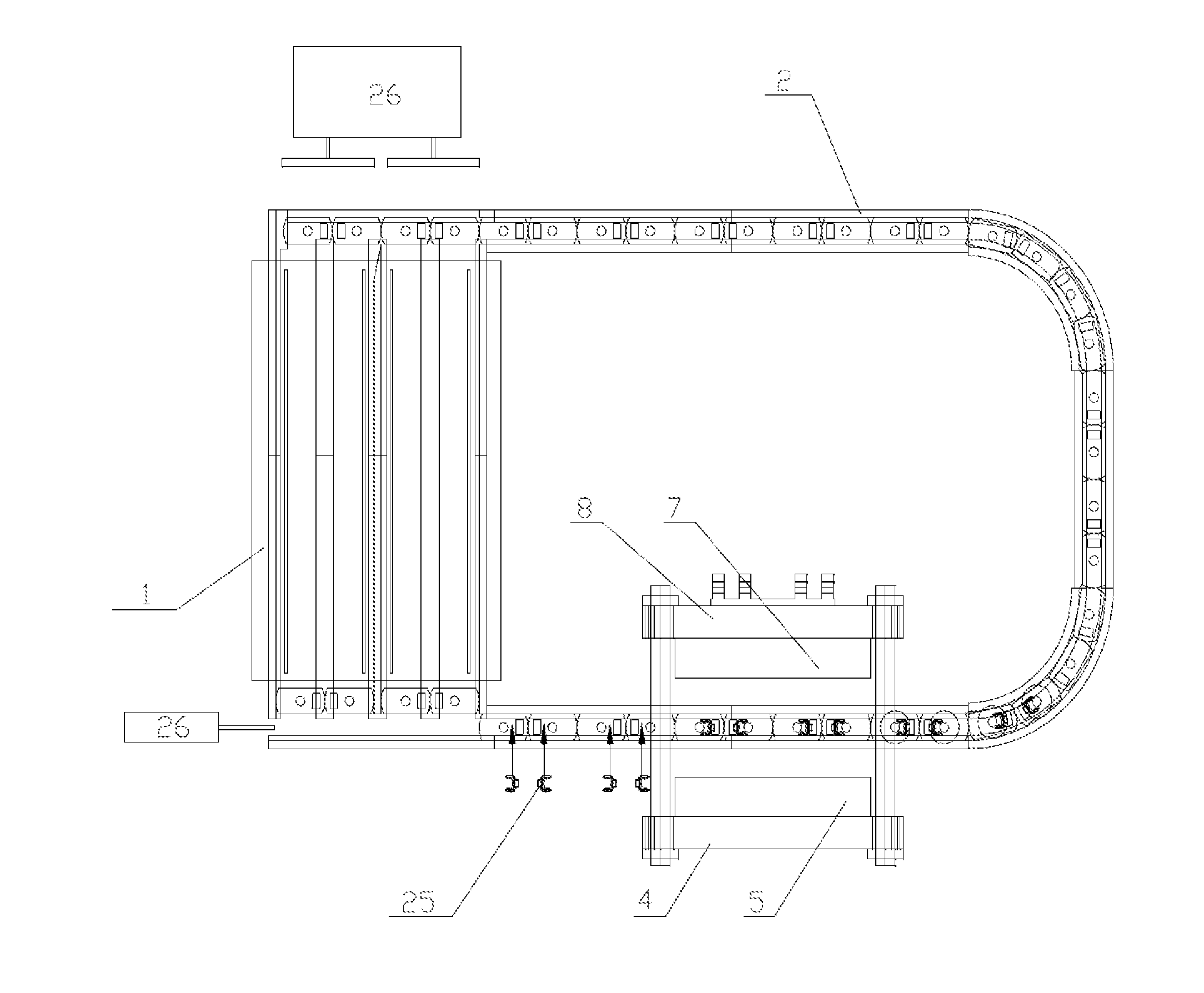
[0057]A handle positioning apparatus outside mould for pre-inserted-handle bottle blow moulding machine is provided on a bottle preform conveying track 2 as shown in FIG. 6; FIG. 3 or FIG. 4 shows a detailed structure of the handle positioning apparatus outside mould for pre-inserted-handle bottle blow moulding machine, which comprises a sliding block base 9, a handle positioning assembly and a bottle preform positioning assembly; the bottle preform positioning assembly is provided in a middle part of the sliding block base 9; the handle positioning assembly is provided at a first end of the sliding block base 9; the handle positioning assembly comprises a positioning base 10, a left positioning panel 11, a right positioning panel 12 and a press block 13; the positioning base 10 is fixedly provided on the first end of the sliding block base 9; the left positioning panel 11 and the right positioning panel 12 are symmetrically provided on the positioning base 10; the press block 13 is...


PUM

PropertyMeasurementUnit
shapeaaaaaaaaaa
transmissionaaaaaaaaaa
volumeaaaaaaaaaa

Abstract

A handle positioning apparatus outside mould for pre-inserted-handle bottle blow moulding machine, and a method of use thereof. The apparatus comprises a sliding block base, a handle positioning assembly, and a bottle pre-form positioning assembly. The bottle pre-form positioning assembly is provided in the middle of the sliding block base, and the handle positioning assembly is provided at one end of the sliding block base. The method of use thereof involves the handle positioning apparatus outside mould carrying a bottle pre-form being placed on a bottle pre-form conveying track; at the awaiting blow moulding position, a handle is placed into the handle positioning apparatus outside mould, and the same is transported into the mould where the bottle will be blown and once completed, is discharged via the bottle pre-form conveying track.

Description

BACKGROUND OF THE INVENTION[0001]The present invention relates to the technical field of blow moulding, and more specifically relates to a handle positioning apparatus outside mould for pre-inserted-handle bottle blow moulding machine, and a method of use thereof.[0002]Polyethylene terephthalate (PET) bottles equipped with handles are not mainstream products in the market of packaging products, but they are necessary in the market of middle to high volume PET bottles. For example, they are quite commonly used for bottling cooking oil and sauces. Furthermore, PET bottles are gradually substituting traditional glass bottles due to a number of disadvantages existing in glass bottles, for example fragility, heavy weight, high energy consumption during the process of manufacturing and high transportation cost etc. Nowadays, there are mainly two methods for manufacturing PET bottles equipped with handles:[0003]Pre-inserted-handle bottle: a bottle is blown by placing a handle and a preform...

Claims


Application Information

Patent Timeline
Patent Type & Authority Applications(United States)
IPC IPC(8): B29C49/20
CPCB29C2049/2078B29C49/20B29C2049/2017B29C2049/2039B29L2031/7158B29C49/42B29C49/22
Inventor ZHANG, KEQIANG
Owner GUANGZHOU ZHANGLIN PLASTIC PRODS
Learn More