Ball bearing

a ball bearing and ball bearing technology, applied in the direction of bearings, shafts and bearings, rotary machine parts, etc., can solve the problems of increasing costs and achieve the effect of reducing the shear resistance of greas

Active Publication Date: 2018-12-11
JTEKT CORP
View PDF9 Cites 2 Cited by
  • Summary
  • Abstract
  • Description
  • Claims
  • Application Information

AI Technical Summary

Benefits of technology

[0007]An object of the present invention is to provide a ball bearing that can reduce shear resistance of grease inside the bearing.

Problems solved by technology

However, in this case, in addition to a raceway groove 92c of the outer ring 92, the inner peripheral surfaces in the shoulder portions 92a of the outer ring 92 need to be ground, which increases cost.

Method used


Image

  • Ball bearing
  • Ball bearing
  • Ball bearing

Examples


Embodiment Construction

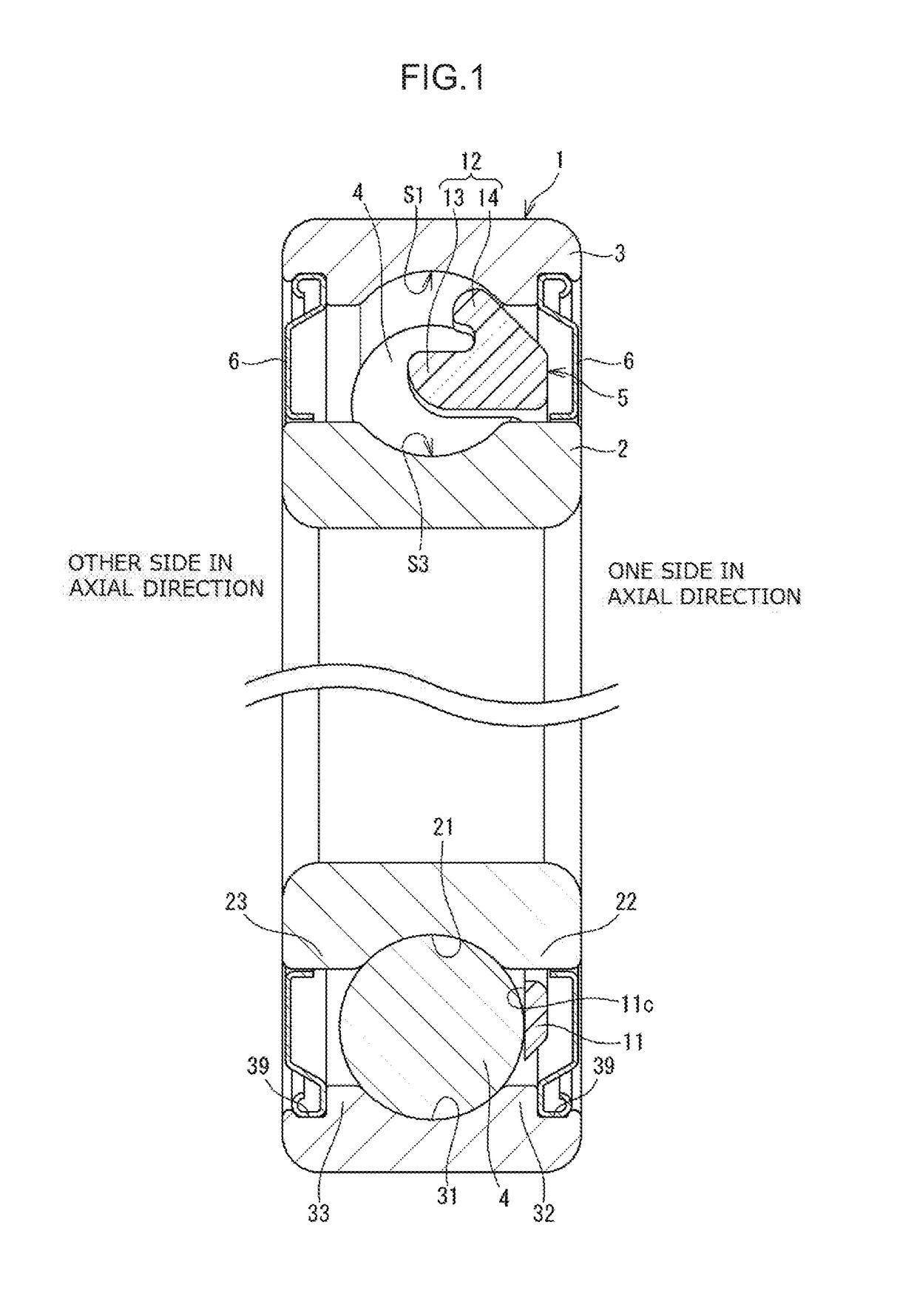
[0019]Embodiments of the present invention will now be described with reference to the drawings. FIG. 1 is a sectional view illustrating a ball bearing according to one embodiment of the present invention. This ball bearing 1 includes an inner ring 2, an outer ring 3, a plurality of balls 4, and an annular cage 5. The outer ring 3 is provided on the outside of the inner ring 2 in a radial direction. The balls 4 are interposed between the inner ring 2 and the outer ring 3. The cage 5 holds these balls 4.

[0020]The ball bearing 1 depicted in FIG. 1 further includes sealing devices 6 on respective opposite sides of the ball bearing 1 in an axial direction. These sealing devices 6 prevent grease in the inside of the bearing in which the balls 4 and the cage 5 are provided from leaking outside. The scaling devices 6 also have a function of preventing external foreign matter from entering the inside of the bearing.

[0021]The inner ring 2 is an annular member, and on the outer periphery ther...


PUM

PropertyMeasurementUnit
areaaaaaaaaaaa
radial dimensionaaaaaaaaaa
distanceaaaaaaaaaa

Abstract

A ball bearing includes an inner ring having an outer periphery in which an inner raceway groove is formed, an outer ring having an inner periphery in which an outer raceway groove is formed, a plurality of balls interposed between the inner raceway groove and the outer raceway groove, and an annular cage that holds the balls. The cage includes an annular portion positioned on one side in an axial direction with respect to the balls and a plurality of cage bar portions that extends from the annular portion toward the other side in the axial direction. Each cage bar portion has a guide portion, and this guide portion positions the cage by coming into contact with the outer raceway groove at one location in a non-contact area other than an area in which the corresponding ball is in contact with the outer raceway groove.

Description

INCORPORATION BY REFERENCE[0001]The disclosure of Japanese Patent Application No. 2015-146650 filed on Jul. 24, 2015 including the specification, drawings and abstract, is incorporated herein by reference in its entirety.BACKGROUND OF THE INVENTION1. Field of the Invention[0002]The present invention relates to a ball bearing.2. Description of Related Art[0003]A ball bearing is a bearing requiring torque (rotational resistance) lower than that of a roller bearing such as a tapered roller bearing, and further torque reduction has been required recently. As depicted in FIG. 8, a conventional ball bearing has an inner ring 91, an outer ring 92, a plurality of balls 93, and an annular cage 94. The balls 93 are held by the cage 94 so as to be spaced apart from each other in the circumferential direction. The cage 94 is guided (positioned) by the balls 93 (see Japanese Patent Application Publication No. 2014-70669 (JP 2014-70669 A), for example). In a ball bearing 90 depicted in FIG. 8, in...

Claims


Application Information

Patent Timeline
Patent Type & Authority Patents(United States)
IPC IPC(8): F16C19/06F16C33/41F16C33/38
CPCF16C33/3806F16C33/416F16C2220/04F16C19/06F16C19/16F16C33/414
Inventor KAMAMOTO, SHIGEOMURATA, JUNJISHISHIHARA, YUKINAKAZAWA, KUNISHIGE
Owner JTEKT CORP
Why Eureka
Try Eureka