Roller shear

A technology of rolling shears and moving frames, which is applied in the direction of shearing devices, shearing machine equipment, and accessories of shearing machines, etc. It can solve the problems of high energy consumption, large space occupation, and small shearing resistance, and achieve high shearing quality. The effect of high height, small equipment footprint and low shear resistance

Pending Publication Date: 2022-05-27
SHANXI TAIGANG ENG TECH
View PDF7 Cites 0 Cited by
  • Summary
  • Abstract
  • Description
  • Claims
  • Application Information

AI Technical Summary

Problems solved by technology

[0004] In fact, if figure 2 In the cutting process of the traditional shearing machine shown, the upper and lower cutting blades are fixed cutting blades, and the plate and strip are cut in a staggered moment. The resistance is large, the required motor power is large, and the energy consumption is high; image 3 As shown in the existing disc shears, the upper and lower cutting blades are all in the form of disc shears. When cutting, the disc shears have no transmission device and no pressing part. They are only driven by hydraulic cylinders to drive the shear. The shears rotate passively, the shearing resistance is small, the energy consumption is low, but the shearing quality is poor
[0005] In short, the transmission shearing machine has the following problems: large shearing resistance, high energy consumption during operation, large volume, and large space occupation; and the existing disc shears have the problem of poor shearing quality

Method used


Image

  • Roller shear
  • Roller shear
  • Roller shear

Examples


Embodiment Construction

[0047] In order to make the objectives, technical solutions and advantages of the present invention clearer, the technical solutions of the present invention will be clearly and completely described below with reference to the specific embodiments of the present invention and the corresponding drawings. Obviously, the described embodiments are only some, but not all, embodiments of the present invention. Based on the embodiments of the present invention, all other embodiments obtained by those of ordinary skill in the art without creative work fall within the protection scope of the present invention.

[0048] The technical solutions provided according to the embodiments of the present invention will be described in detail below with reference to the accompanying drawings.

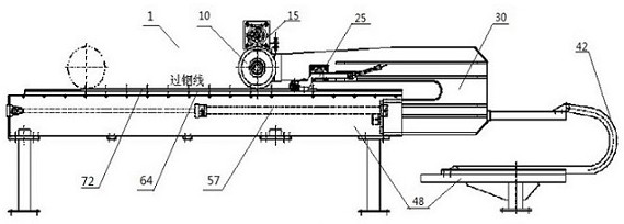
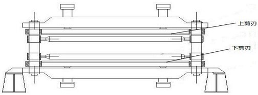
[0049] see figure 1 , according to an embodiment of the present invention, a roller 1 is provided for shearing strips, wherein the roller shear 1 includes: an upper cutting edge 10, see Figure 4 , which...


PUM

PropertyMeasurementUnit
porosityaaaaaaaaaa
thicknessaaaaaaaaaa

Abstract

The invention discloses a roller shear which is used for shearing plates and strips. The roller shear comprises an upper shear blade in the shape of a circle shear; the upper shear blade, the transmission system, the gap adjusting device and the height adjusting device are mounted on the movable frame; the transmission system comprises a hydraulic motor, a planetary reducer, a chain wheel and a roller chain; the hydraulic cylinder pushes the moving frame to move along the sliding rail; the support is composed of a machined part, a welded part, channel steel and the like, and a sliding rail is installed on the support; the movable frame is connected with the bracket through the drag chain; the lower shear blade is mounted on the bracket; the gap adjusting device comprises a ratchet wrench and a swing arm, a bearing is arranged below the swing arm, a roller is arranged at the front section below the swing arm, and the distance between the bearing and the sliding rail is adjusted through the wrench and the swing arm; the height adjusting device mainly comprises a bolt, a nut and a key and is used for adjusting the height of the upper shear blade. The shearing resistance is reduced, the shearing quality is improved, the movable frame can be moved away after shearing of the roller shear, and the space is saved.

Description

technical field [0001] The present invention relates to the technical field of processing equipment such as sheet and strip, in particular to a rolling shear. Background technique [0002] In the plate and strip production process, the shearing machine is indispensable. The high-quality shearing of the shearing machine can reduce the scrap rate, save the production cost of the plate and strip, improve the yield, and increase the economic benefit of the whole plate and strip production line. [0003] Generally speaking, if figure 1 As shown, in the production process of shearing the plate and strip, it is necessary to realize the shearing of the plate and strip through the upper shearing edge 2 and the lower shearing edge 10 . Typically, in the shearing process, first, the transmission system 3 drives the upper shearing blade 2 to roll and shear, and at the same time, the hydraulic cylinder 8 pushes the moving frame 5 to move, and the rolling shearing and the movement of the...

Claims


Application Information

Patent Timeline
Patent Type & Authority Applications(China)
IPC IPC(8): B23D19/04B23D33/00
CPCB23D19/04B23D33/00Y02P70/10
Inventor 王鹏洲张春晓郝晋忠张扬李哲
Owner SHANXI TAIGANG ENG TECH
Why Eureka
Try Eureka