Gas distribution system, reactor including the system, and methods of using the same

a technology of gas distribution system and gas phase reactor, which is applied in the direction of transportation and packaging, energy-based chemical/physical/physico-chemical processes, coatings, etc., can solve the problems of system inability to adequately address uniform film properties and generally inability to independently control film properties

Active Publication Date: 2019-01-01
ASM IP HLDG BV
View PDF1301 Cites 309 Cited by
  • Summary
  • Abstract
  • Description
  • Claims
  • Application Information

AI Technical Summary

Benefits of technology

[0006]Various embodiments of the present disclosure relate to gas distribution systems, gas-phase reactor systems including a gas distribution systems, and to methods of using the gas distribution and reactor systems. While the ways in which various embodiments of the present disclosure address drawbacks of prior gas distribution systems and reactor systems are discussed in more detail below, in general, various embodiments of the disclosure provide gas distribution systems that include multiple ports, wherein a flow rate to one or more of the ports can be independently controlled. Various ports can be coupled to different gas sources to allow fine tuning of reactants provided to a substrate surface. In addition, exemplary gas distribution systems allow for independent tuning of film properties, such as film thickness, film thickness uniformity, and film resistivity.
[0007]In accordance with exemplary embodiments of the disclosure, a gas distribution system includes a flange that includes one or more first gas expansion ports formed within the flange, one or more second gas expansion ports formed within the flange, one or more first gas channels formed within the flange, wherein each of the one or more first gas channels terminate at one of the one or more of the first gas expansion ports, and one or more second gas channels formed within the flange, wherein the one or more second gas channels terminate at one or more of the second gas expansion ports. Exemplary flanges can also include one or more first conduits, wherein each first conduit is in fluid communication between a first expansion port and a reaction chamber and one or more second conduits, wherein each second conduit is in fluid communication between a second expansion port and the reaction chamber. In accordance with various aspects of these embodiments, the one or more first gas channels are fluidly coupled to a precursor source, such as a precursor source selected from the group consisting of trichlorosilane, dichlorosilane, silane, disilane, trisilane, and other semiconductor layer precursor sources. In accordance with further aspects, one or more second gas channels are coupled to a dopant source, such as a source comprising As, P, C, Ge, and B, with or without a carrier gas, such as hydrogen, nitrogen, argon, or the like. Both the precursor source and the dopant source can include suitable dopants, such as As, P, C, Ge, and B. In accordance with some exemplary aspects, one or more first gas expansion ports and one or more second gas expansion ports are adjacent each other—e.g., in a front-to-back configuration relative to gas flow in a reaction chamber, to facilitate localized mixing of the first gas and the second gas. To allow fine tuning of various film or reactant properties, the gas distribution system can include an independent control valve fluidly coupled to each of the one or more first gas channels and / or to one or more of the second gas channels. This can allow independent control of gas to one or more of the first gas expansion ports and the second gas expansion ports and the respective conduits. Further, in accordance with exemplary aspects of these embodiments, two or more of the first gas channels and / or the second gas channels are coupled together upstream of the flange—e.g., between a respective gas source and a valve coupled to an expansion port. Various gas distribution systems described herein allow independent tuning of film properties across a surface of a substrate—e.g., properties near an edge of the substrate can be tuned independently from film properties away from the edge of the substrate.

Problems solved by technology

However, such systems do not adequately address uniformity of film properties, particularly at or near an edge of a substrate.
Additionally, such systems generally do not allow for independent control of film properties, such as film thickness uniformity and resistivity.

Method used


Image

  • Gas distribution system, reactor including the system, and methods of using the same
  • Gas distribution system, reactor including the system, and methods of using the same
  • Gas distribution system, reactor including the system, and methods of using the same

Examples


Embodiment Construction

[0016]The description of exemplary embodiments provided below is merely exemplary and is intended for purposes of illustration only; the following description is not intended to limit the scope of the disclosure or the claims. Moreover, recitation of multiple embodiments having stated features is not intended to exclude other embodiments having additional features or other embodiments incorporating different combinations of the stated features.

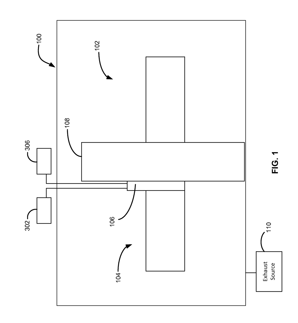
[0017]The present disclosure generally relates to gas distribution systems, to reactor systems including a gas distribution system, and to methods of using the gas distribution systems and reactor systems. Gas distribution systems and reactor systems including a gas distribution system as described herein can be used to process substrates, such as semiconductor wafers, in gas-phase reactors. By way of examples, the systems described herein can be used to form or grow epitaxil layers (e.g., doped semiconductor layers) on a surface of a substrat...


PUM

PropertyMeasurementUnit
widthaaaaaaaaaa
widthaaaaaaaaaa
widthaaaaaaaaaa

Abstract

A gas distribution system, a reactor system including the gas distribution system, and method of using the gas distribution system and reactor system are disclosed. The gas distribution system can be used in gas-phase reactor systems to independently fine tune gas source locations and gas flow rates of reactants to a reaction chamber of the reactor systems.

Description

FIELD OF DISCLOSURE[0001]The present disclosure generally relates to gas-phase reactors and systems. More particularly, the disclosure relates to gas distribution systems for gas-phase reactors, to reactor systems including a gas distribution system, and to methods of using the gas distribution systems and reactor systems.BACKGROUND OF THE DISCLOSURE[0002]Gas-phase reactors, such as chemical vapor deposition (CVD), plasma-enhanced CVD (PECVD), atomic layer deposition (ALD), and the like can be used for a variety of applications, including depositing and etching materials on a substrate surface. For example, gas-phase reactors can be used to deposit and / or etch layers on a substrate to form semiconductor device, flat panel display devices, photovoltaic devices, microelectromechanical systems (MEMS), and the like.[0003]A typical gas-phase reactor system includes a reactor including a reaction chamber, one or more precursor gas sources fluidly coupled to the reaction chamber, one or mo...

Claims


Application Information

Patent Timeline
Patent Type & Authority Patents(United States)
IPC IPC(8): C23C16/455C23C16/52
CPCC23C16/52C23C16/45502C23C16/45523C23C16/45574C23C16/45561Y10T137/87877Y10T137/87249B01J19/08B01J19/26B01J2219/00351
Inventor HAWKINS, MARKHALLECK, BRADLEY LEONARDKIRSCHENHEITER, TOMHOSSA, BENJAMINPOTTEBAUM, CLAYMISKYS, CLAUDIO
Owner ASM IP HLDG BV
Why Eureka
Try Eureka