
Dual 4-port electromagnetic valve

a technology of electromagnetic valves and electromagnetic valves, applied in valve housings, valve operating means/releasing devices, transportation and packaging, etc., can solve problems such as difficulty in placing such electromagnetic valves, and achieve the effect of making the length of electromagnetic valves much shorter

Active Publication Date: 2019-01-08
SMC CORP
View PDF16 Cites 4 Cited by
  • Summary
  • Abstract
  • Description
  • Claims
  • Application Information

AI Technical Summary

Benefits of technology

This design significantly reduces the length of the electromagnetic valve, allowing it to be more compact and suitable for placement on manifolds or sub-plates, while maintaining the functionality of two 4-port valves in a single unit.

Problems solved by technology

Therefore, the width of a manifold electromagnetic valve tends to be large, leading to a problem in that, for example, it is difficult to place such a manifold electromagnetic valve if the site for placing the valve is limited.
Although the electromagnetic valve disclosed by PTL 1 is a 3-port valve, the above problem also applies to 4-port valves.

Method used


Image

  • Dual 4-port electromagnetic valve
  • Dual 4-port electromagnetic valve
  • Dual 4-port electromagnetic valve

Examples


first embodiment

[0072]Conversely, the configuration for returning the two spools 8a and 8b of the electromagnetic valve 1C to the first switching positions may be the same as that of the electromagnetic valve 1A according to the

third embodiment

[0073]FIGS. 12 and 13 illustrate applications of the electromagnetic valve 1C according to the

[0074]In a first application illustrated in FIG. 12, the first and second output ports A1 and A2 are closed by port plugs 51 and are not usable, whereas the third and fourth output ports B1 and B2 are provided with the pipe joints 15B and are usable.

[0075]As with the pipe joints 15B, the port plugs 51 have locking grooves 48 at which the edges of the recesses 47a of the attaching plate 47 are locked, respectively. The port plugs 51 are also provided with O rings 50, respectively. The port plugs 51 are attached to the output ports A1 and A2 with the aid of the attaching plate 47, along with the pipe joints 15B for the third and fourth output ports B1 and B2.

[0076]Thus, the electromagnetic valve 1C has substantially the same configuration as a combination of two 3-port valves. Moreover, the electromagnetic valve 1C has a function as a normally closed 4-position valve in which the first and se...


PUM


Abstract

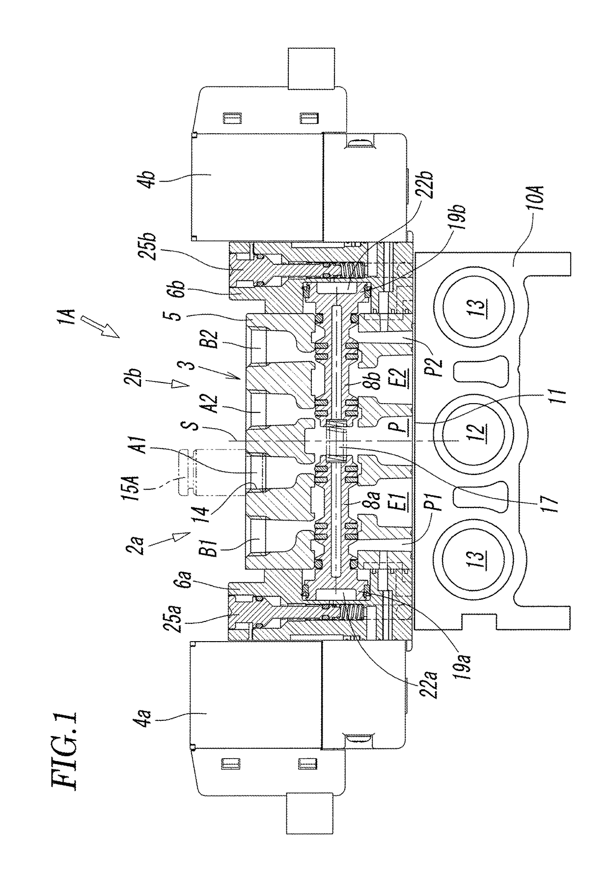
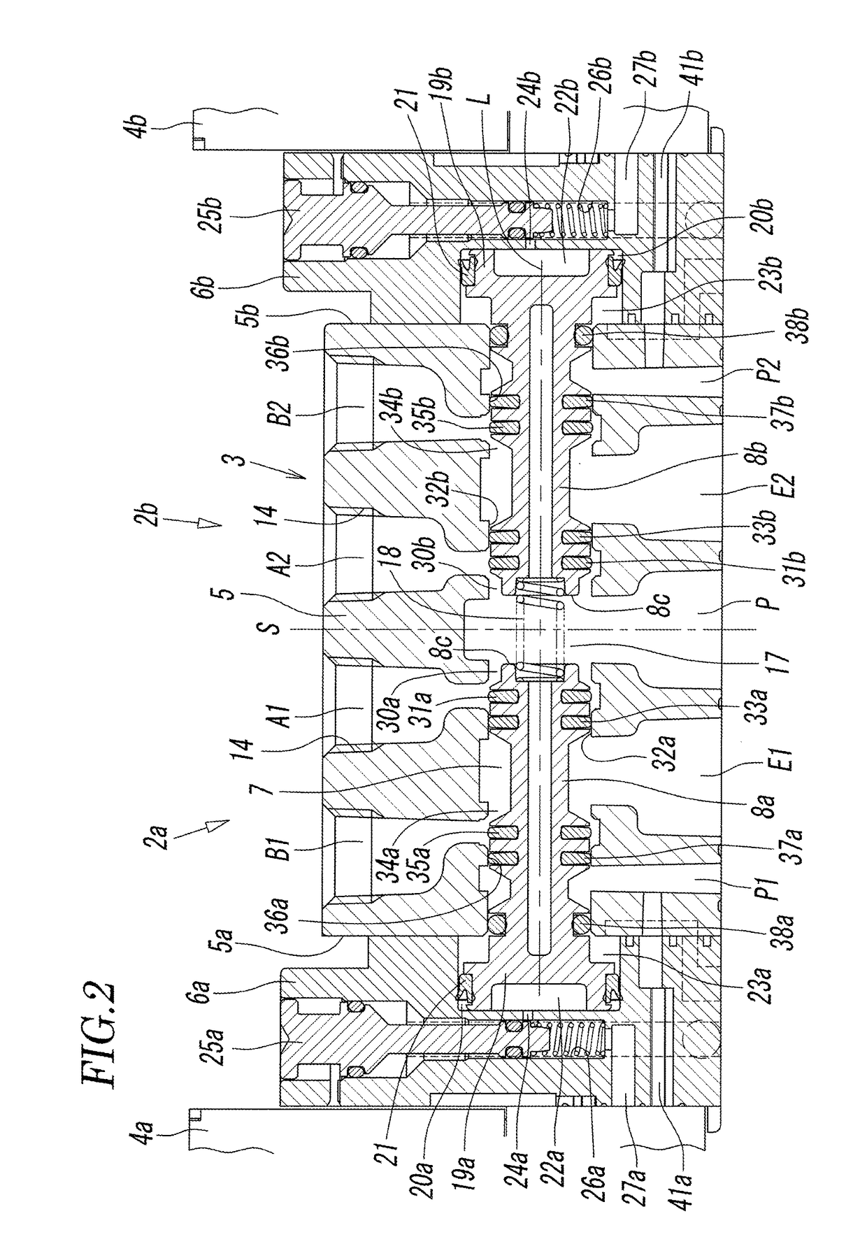
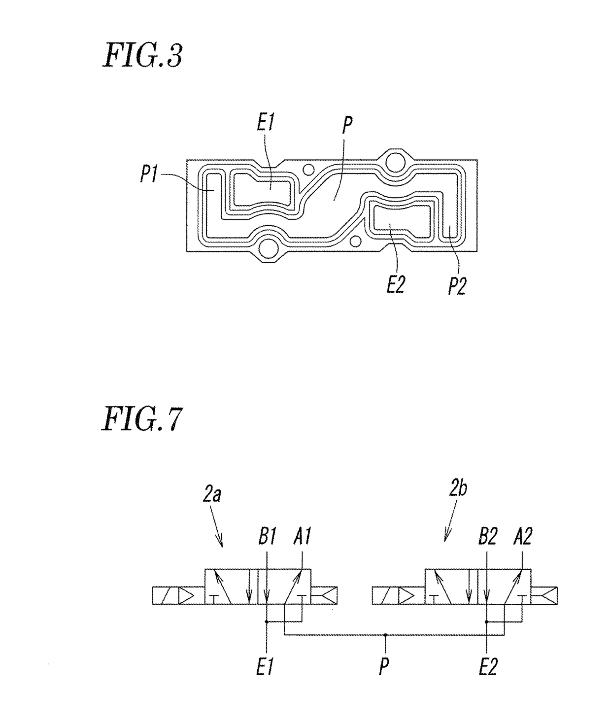
[Object] To provide a compact, rationally designed, dual 4-port electromagnetic valve that is an electromagnetic valve having functions of two 4-port valves.[Solution] A dual 4-port electromagnetic valve includes two spools (8a, 8b) slidable independently of each other in a valve hole (7); two pilot valves (4a, 4b) that drive the two spools, respectively; a main supply port (P) that communicates with the valve hole (7) at a position where the two spools face each other; first and second output ports (A1, A2) that communicate with the valve hole (7) on two respective sides of the main supply port (P), first and second discharge ports (E1, E2) that communicate with the valve hole (7) on two respective outer sides of the output ports (A1, A2), third and fourth output ports (B1, B2) that communicate with the valve hole (7) on two respective outer sides of the discharge ports (E1, E2), and first and second supply ports (P1, P2) that communicate with the valve hole (7) on two respective outer sides of the output ports (B1, B2). The main supply port (P) and each of the first and second supply ports (P1, P2) communicate with each other.

Description

TECHNICAL FIELD[0001]The present invention relates to a dual 4-port electromagnetic valve having functions of two 4-port valves.BACKGROUND ART[0002]Hitherto, if a plurality of electromagnetic valves is used as one unit, the plurality of electromagnetic valves is mounted on a manifold, whereby a manifold electromagnetic valve is obtained, in general. In such a case, to efficiently mount as many electromagnetic valves as possible on a manifold, two electromagnetic valves arranged face to face are paired, and a plurality of such pairs of electromagnetic valves are arranged side by side on a manifold, as disclosed by, for example, PTL 1. Thus, the length of such a manifold electromagnetic valve can be reduced to about half the length of the same number of electromagnetic valves that are arranged side by side in one line on a manifold.[0003]However, a pair of electromagnetic valves that are arranged face to face projects by a large length from the manifold in the width direction. Therefo...

Claims


Application Information

Patent Timeline
Patent Type & Authority Patents(United States)
IPC IPC(8): F15B13/08F16K11/24F16K11/20F16K31/383F16K27/00F16K11/07F16K27/04F16K31/00F16K31/42
CPCF15B13/0814F15B13/0842F16K11/07F16K11/207F16K11/24F16K27/00F16K31/383F16K31/426F16K27/04Y10T137/86622F16K31/00Y10T137/86574Y10T137/86582F16K2200/301F16K11/00F16K31/02
Inventor MIYAZOE, SHINJIYOSHIMURA, SHINICHIMURAKAMI, TAKASHI
Owner SMC CORP
Learn More