Electronic timepiece

a technology of electronic timepieces and timepieces, applied in the field of electronic timepieces, can solve the problems of causing eddy currents, and reducing the sensitivity of the receiving antenna

Active Publication Date: 2019-01-15
CASIO COMPUTER CO LTD
View PDF15 Cites 1 Cited by
  • Summary
  • Abstract
  • Description
  • Claims
  • Application Information

AI Technical Summary

Benefits of technology

[0013]An object of the present invention is to provide an electronic timepiece capable of securing the radio-wave reception performance of an antenna while securing the operation accuracy of motors.

Problems solved by technology

However, the antimagnetic plates are made of a material having high relative-permeability, and if such members having high relative-permeability are disposed near the antenna, it becomes easier for eddy current to occur, and loss of electric energy (eddy-current loss) occurs, whereby the receiving sensitivity of the antenna decreases.
However, in a case where an electronic timepiece is a small instrument such as a wristwatch, since every module should be assembled in a limited space of the inside of a case, inevitably, motors and an antenna are disposed close to one another.
However, significant manufacturing cost is required in making the antimagnetic plates in different shapes, and the shapes of the antimagnetic plates should be changed depending on the assembly position of the antenna.
Therefore, there is a problem that it is impossible to commoditize the antimagnetic plates.
Further, according to the layout of the motors and the antenna, even though the antimagnetic plates have different shapes, it may be difficult to provide sufficient distances between each antimagnetic plate and the antenna, and it may be apprehended that the receiving sensitivity of the antenna will decrease.
In an electronic timepiece which performs time correction on the basis of a standard radio wave, a decrease in the receiving sensitivity of an antenna causes the intrinsic timepiece performance to deteriorate.

Method used


Image

  • Electronic timepiece
  • Electronic timepiece
  • Electronic timepiece

Examples


first embodiment

[0040][First Embodiment]

[0041]First, with reference to FIGS. 1 to 7, a first embodiment of an electronic timepiece according to the present invention will be described. Hereinafter, an electronic timepiece will be referred to simply as a “timepiece”.

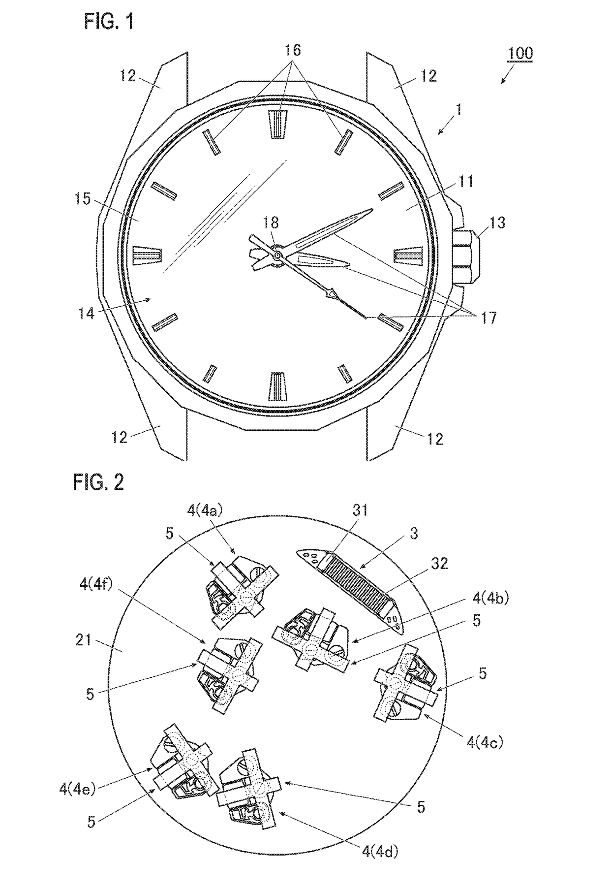
[0042]FIG. 1 is a plan view illustrating a timepiece (an electronic timepiece) according to the present invention.

[0043]As shown in FIG. 1, a timepiece 100 according to the present embodiment has a case (referred to as “timepiece case 1” in the following embodiments). The timepiece case 1 is made of, for example, a metal such as stainless steel or titanium, ceramic, or various synthetic resins. However, a material for making the timepiece case 1 is not limited to those examples.

[0044]The timepiece case 1 of the present embodiment is formed in a short column shape having a hollow, and on the front side of the timepiece 100 (the viewable side of the timepiece), a windshield member 11 made of transparent glass or the like is attached.

[0045]...

second embodiment

[0159][Second Embodiment]

[0160]Now, a second embodiment of the electronic timepiece according to the present invention will be described with reference to FIG. 11. Since the present embodiment is different from the first embodiment only in the configuration of antimagnetic plates, particularly, the difference from the first embodiment will be described below.

[0161]FIG. 11 is a plan view illustrating an antenna and motors provided inside a module according to the present embodiment.

[0162]As shown in FIG. 11, in the present embodiment, similarly in the first embodiment, one antenna 3 and six motors 4 (motors 4a to 4f) are disposed on a main plate 21, which is assembled in the module.

[0163]Further, at least with respect to some (in FIG. 11, the motors 4a to 4c) of the plurality of motors 4 (in the present embodiment, the motors 4a to 4f) disposed in a predetermined range from the antenna 3, individual antimagnetic plates 5 identical to those of the first embodiment are disposed, respec...

third embodiment

[0193][Third Embodiment]

[0194]Now, a third embodiment of the electronic timepiece according to the present invention will be described with reference to FIG. 13. Since the present embodiment is different from the first embodiment and the like only in the configuration of antimagnetic plates, particularly, the difference from the first embodiment and the like will be described below.

[0195]FIG. 13 is a plan view illustrating an antenna and motors provided inside a module according to the present embodiment.

[0196]As shown in FIG. 13, in the present embodiment, similarly in the first embodiment, one antenna 3 and six motors 4 (motors 4a to 4f) are disposed on a main plate 21, which is assembled in the module.

[0197]Further, with respect to the plurality of motors 4 (in the present embodiment, the motors 4a to 4f), belt-like individual antimagnetic plates 9 (in FIG. 13, individual antimagnetic plates 9a to 9f) configured to have widths equal to or greater than the diameters of the rotor m...


PUM


Abstract

In a timepiece 100 having an antenna 3 and motors 4, each motor 4 includes a stator 41, a coil 42 magnetically connected to the stator 41, and a rotor magnet 431 disposed in a receiving part 411 of the stator 41. With respect to each motor 4 disposed in a predetermined range from the antenna 3, an individual antimagnetic plate 5 which is a belt-like antimagnetic plate configured to have a width equal to or greater than the diameter of the rotor magnet 431 and cover a portion of the motor 4 including the rotor magnet 431 is disposed.

Description

CROSS-REFERENCE TO RELATED APPLICATION[0001]This application is based upon and claims the benefit of priority from the prior Japanese Patent Application No. 2015-175603, filed on Sep. 7, 2015, and the entire contents of which are incorporated herein by reference.BACKGROUND OF THE INVENTION[0002]The present invention relates to an electronic timepiece.[0003]In the related art, there are known electronic timepieces, each of which has a plurality of motors such as stepping motors, and an antenna for receiving a standard radio wave which is a long radio wave, and performs various operations, such as time correction based on the standard radio wave.[0004]If the operation accuracy of the motors is regarded as important, it is preferable to dispose antimagnetic plates for magnetically shielding the motors from external magnetic fields which may exert influence on the operations of the motors.[0005]However, the antimagnetic plates are made of a material having high relative-permeability, an...

Claims


Application Information

Patent Timeline
Patent Type & Authority Patents(United States)
IPC IPC(8): G04B43/00G04R60/00
CPCG04R60/00G04B43/00G04G21/04G04R20/00G04R60/14G04C3/146
Inventor HOSOBUCHI, HIROYUKIYANO, JUNRO
Owner CASIO COMPUTER CO LTD
Why Eureka
Try Eureka