Rotor magnet driven optical shutter assembly

a technology of optical shutters and magnets, applied in the field of electromagnetically driven optical shutters, can solve the problems of inherently very non-linear force curves, low energy efficiency, high heat, etc., and achieve the effects of low cost manufacturability, simple structure, and long li

Inactive Publication Date: 2007-07-26
CVI LASER
View PDF33 Cites 31 Cited by
  • Summary
  • Abstract
  • Description
  • Claims
  • Application Information

AI Technical Summary

Benefits of technology

[0015] There are stepper motors, particularly electric watch motor drives, that use somewhat similar magnetic circuitry to drive rotors in a step-wise motion. However, the instant invention (to the extent it might be compared to such motors) is novel and non-obvious in its application of a magnetic rotor to directly drive a shutter blade for bidirectional, limited-stroke actuation where the shutter blade is preferably rigidly connected (in terms of rotational motion but not ne

Problems solved by technology

However, most of the aforesaid prior art arrangements of electromagnetic drives for optical shutter actuation involve solenoids, which have inherently very non-linear force curves and low energy efficiency.
This leads to the disadvantages of high heat, high current draw, high impact (and drive linkage wear), and poor speed/position/force control.
Further, many of the prior art arrangements described also involve complex linkages to drive blades, w

Method used


Image

  • Rotor magnet driven optical shutter assembly
  • Rotor magnet driven optical shutter assembly
  • Rotor magnet driven optical shutter assembly

Examples


Embodiment Construction

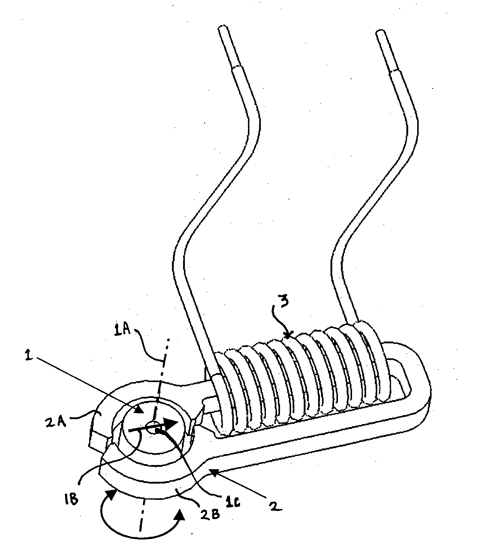
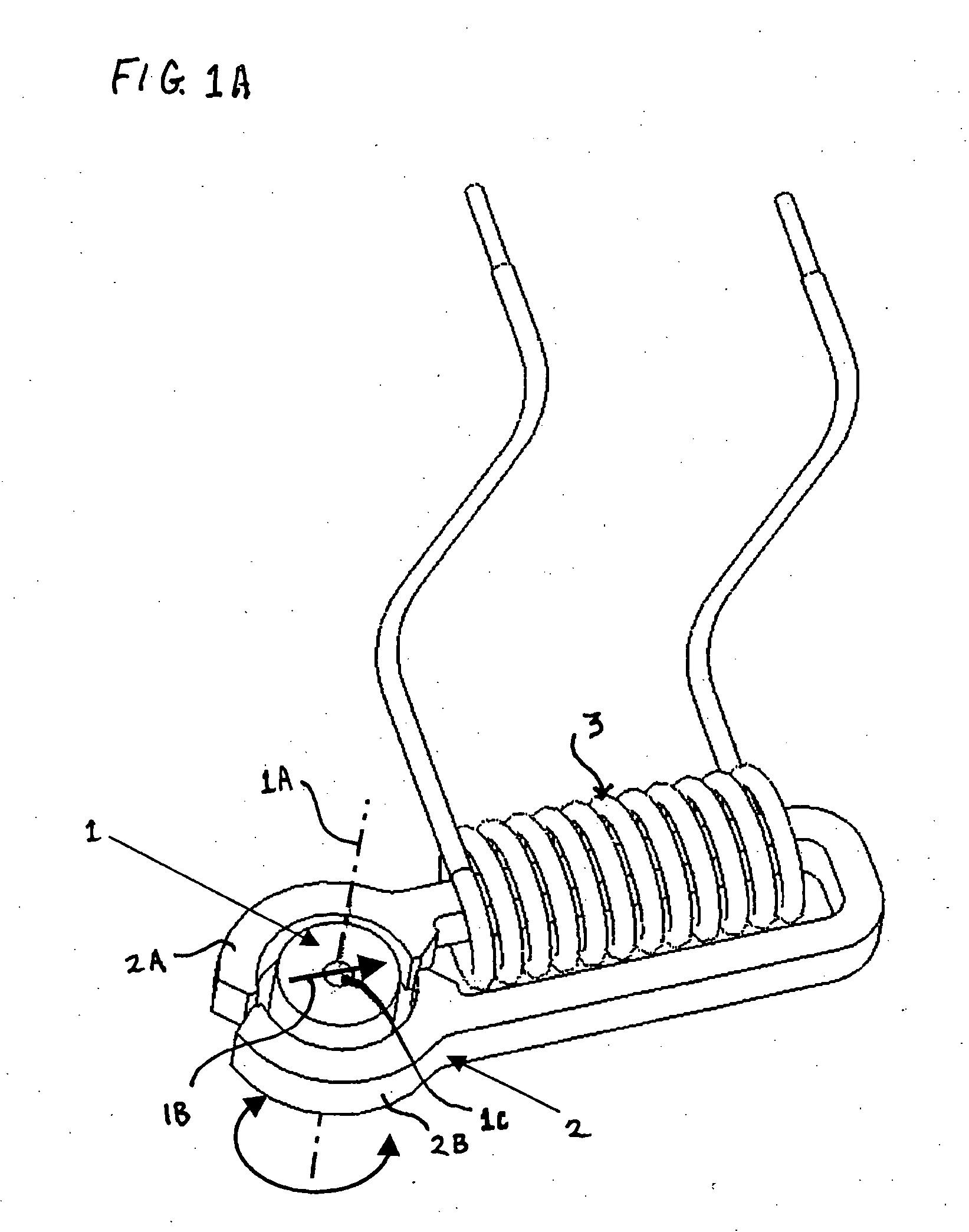
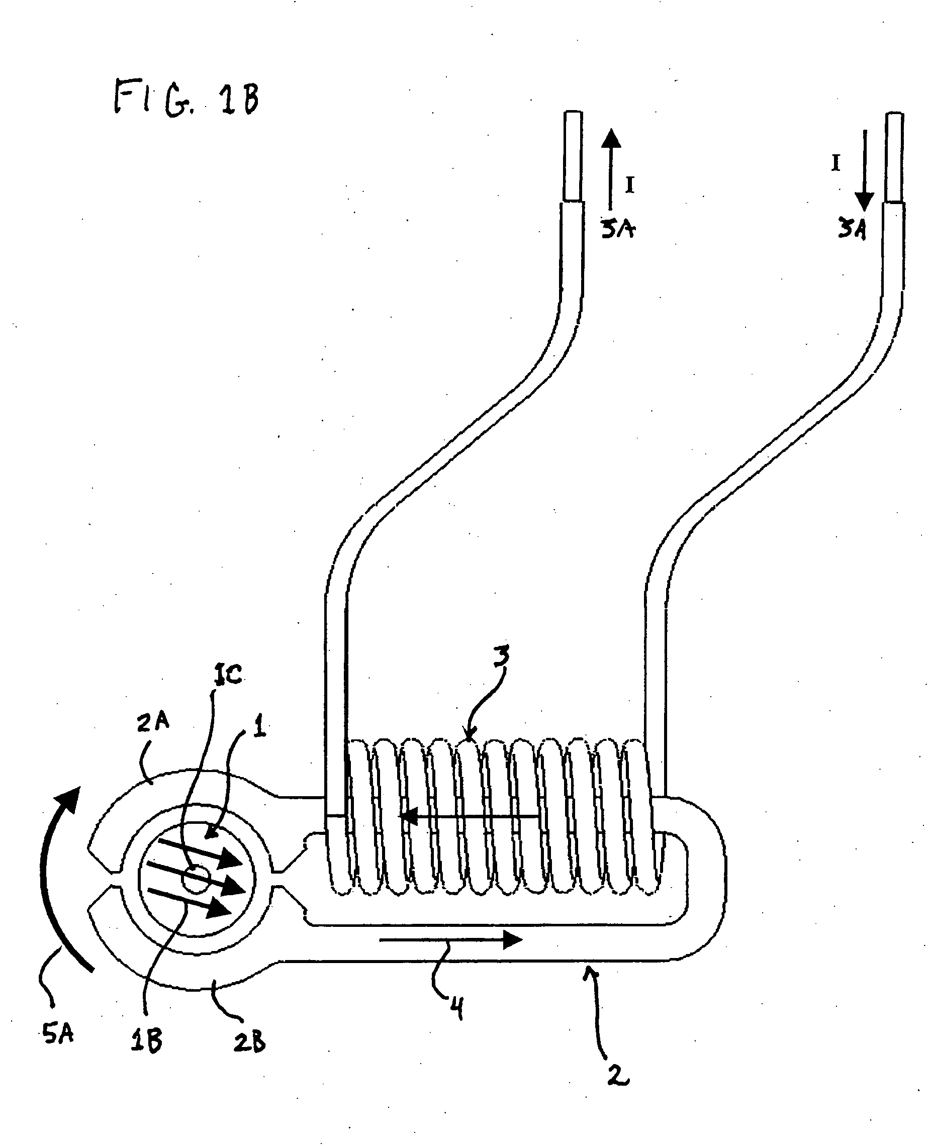
[0050] The basic underlying principles of the invention, as initially set forth in the summary of the invention, can be better understood by reference to FIGS. 1A, 1B, and 1C. In FIG. 1A, a cylindrical rotor magnet 1 rotatable on a central axis 1A and having a polarization denoted by polarization indicator arrow 1B is positioned between first pole 2A and second pole 2B of two arms of a stator 2. (In this specification and in the claims that follow, the term “magnet” is reserved for a non-electromagnet). The position of rotor magnet 1—as indicated by arrow 1B—is initially and illustratively set at a neutral point between poles 2A and 2B in order to show the torques produced by different magnetic polarizations of stator 2. Stator 2 is, in turn, wrapped by an electromagnet drive coil 3 such that its can serve as an electromagnet with its polarization determined by the direction of current in electromagnet drive coil 3.

[0051] In FIG. 1B, the direction of current flow through electromag...


PUM


Abstract

A rotor magnet driven optical shutter assembly with a permanent magnet rotor directly connected to and driving the rotation of an optical shutter blade, to alternately block or allow transmission of light through the shutter aperture. The rotor is cylindrical with optional center hole, is magnetized across its diameter, and rotates around a pivot bearing coaxial with its center axis. A stator is arranged around the rotor and is shaped so that, as the rotor rotates over its range of travel, the flux through the electromagnet drive coil core varies in magnitude and direction. A drive current through the electromagnet drive coil thus induces a torque to the rotor, to open or close the shutter blade. By driving the electromagnet drive coil with a controlled current waveform, the shutter aperture may be opened or closed (either quickly or slowly), held open/closed, or moved to any intermediate position, as desired.

Description

BACKGROUND OF THE INVENTION [0001] 1. Field of the Invention [0002] The invention pertains to the field of electro-magnetically driven optical shutters. More particularly, the invention pertains to a means for opening and closing one or more blades of an optical shutter where the optical shutter blades are directly connected to a rotor magnet. [0003] 2. Description of Related Art [0004] The prior art is replete with examples of electro-magnetically actuated optical shutters. Representative examples of prior art in this area include the following U.S. patents: [0005] U.S. Pat. No. 4,720,726 describes a shutter driving apparatus using a driving current pulse. [0006] U.S. Pat. No. 4,864,346 describes a shutter driving apparatus using pulses to actuate the shutter back and forth. [0007] U.S. Pat. No. 4,864,347 describes a shutter control apparatus using varying pulse rates to vary actuation of the shutter. [0008] U.S. Pat. No. 4,984,003 describes a shutter driving apparatus using a cons...

Claims


Application Information

Patent Timeline
IPC IPC(8): G03B9/08
CPCG03B9/10G03B9/24G03B9/22G03B9/08
Inventor DURFEE, DAVID W.
Owner CVI LASER
Why Eureka
Try Eureka