Wave power assembly with an electromagnetic dampning means

a technology of electromagnetic damping and power assembly, which is applied in the direction of electric generator control, machines/engines, mechanical apparatus, etc., can solve the problems of more even and undisturbed running, and achieve the effects of reducing the risk of mechanical problems of the generator, reducing the risk of generator mechanical problems, and improving the efficiency of electromagnetic energy transformation

Inactive Publication Date: 2008-04-08
SEABASED AB
View PDF14 Cites 30 Cited by
  • Summary
  • Abstract
  • Description
  • Claims
  • Application Information

AI Technical Summary

Benefits of technology

[0020]The result will be that the risk of mechanical problems of the generator is reduced. Furthermore, the electromagnetic transformation of energy will be more favourable in that it becomes more even and having a higher efficiency.
[0021]According to a preferred embodiment of the invented wave power assembly, the stator comprises multiphase winding, and the electromagnetic damping means consists of the stator winding comprising fractional slot winding. Fractional slot winding is a well-tried construction for rotary electric generators and constitutes a simple and expedient way to, by means of the winding geometry, reduce the axial force pulsations.
[0022]According to an additional preferred embodiment, the fractional slot winding has a winding factor that is <1. The advantage of such an embodiment is that it facilitates having less distance between the poles.
[0029]The two embodiments closest above enables a structurally simple way to solely by means of modification of the rotor provide the inclination, wherein the stator can be formed in a conventional way.
[0032]According to an additional preferred embodiment, the rotor is permanent magnetic, which constitutes a simple and expedient embodiment.

Problems solved by technology

By the fact that the generator is provided with means for keeping said pulsations at a relatively low level, the total axial force on the rotor will become much more even than otherwise, which results in more even and more undisturbed running.

Method used


Image

  • Wave power assembly with an electromagnetic dampning means
  • Wave power assembly with an electromagnetic dampning means
  • Wave power assembly with an electromagnetic dampning means

Examples


Embodiment Construction

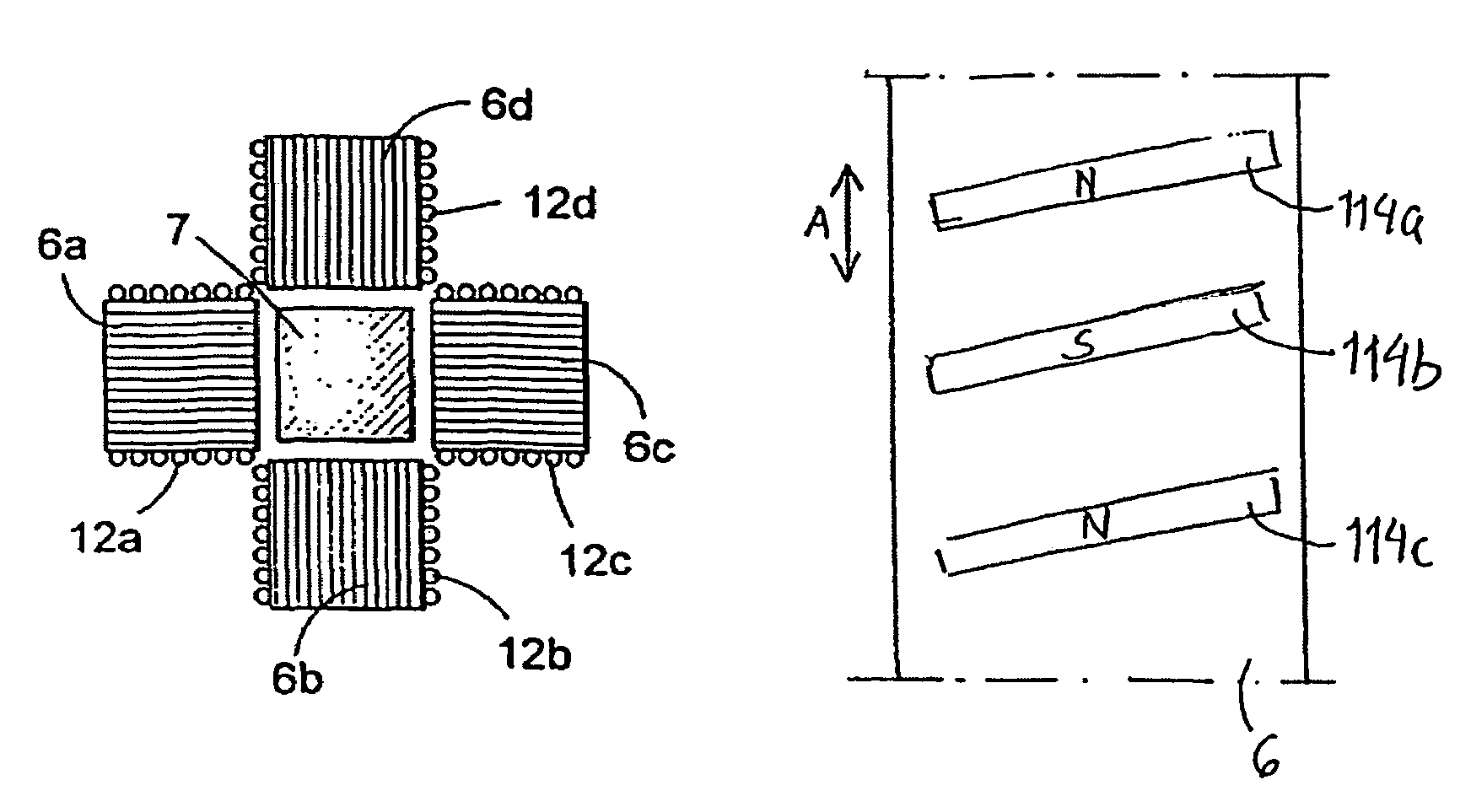
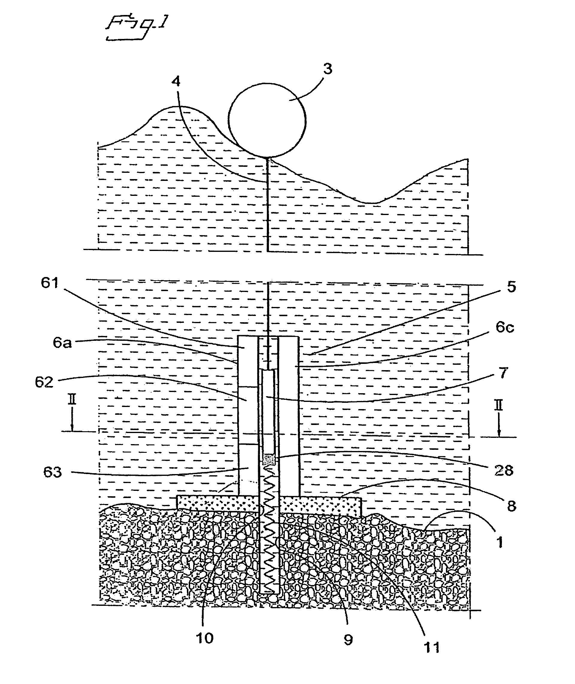
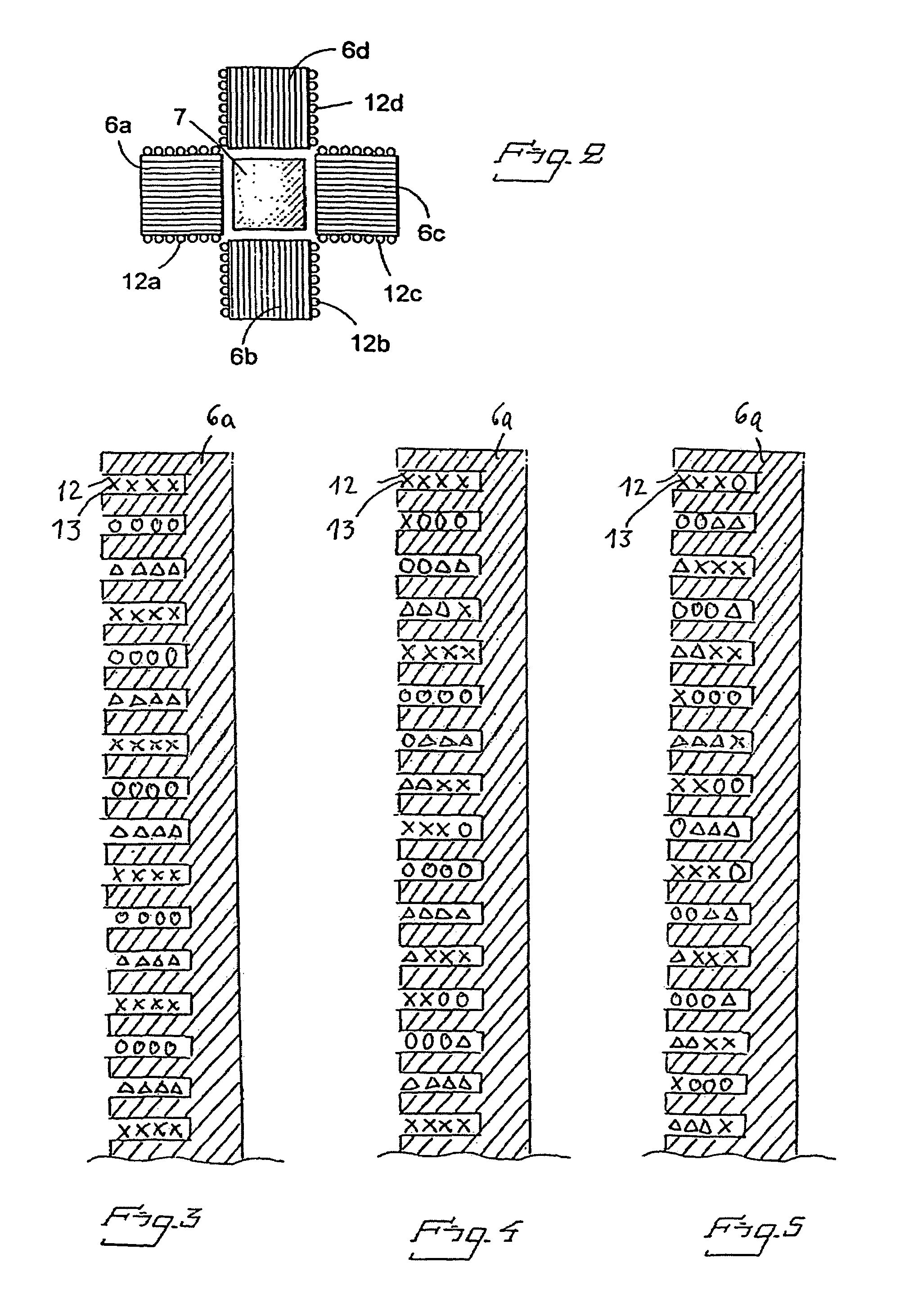
[0047]FIG. 1 illustrates the principle of a wave power assembly according to the invention. A hull 3 is arranged to float on the sea surface 2. Waves impart reciprocating vertical motion to the hull 3. At the bottom 1, a linear generator 5 is anchored via a base plate 8 fastened at the bottom, which plate may be a concrete slab. At the base plate 8, the stator 6a, 6c of the linear generator is fastened. The stator consists of four vertical column-like stator packs, only two of which are visible in the figure. In the space between the stator packs, the rotor 7 of the generator is arranged. The same is connected to the hull 3 by means of a line 4. The rotor 7 is of permanent magnetic material.

[0048]The base plate 8 has a centrally arranged hole 10, and concentrically therewith a bottom hole 9 is recessed in the bottom of the sea. The bottom hole 9 may suitably be lined. At the lower end of the bottom hole 9, a tension spring 11 is fastened, which with the other end thereof is fastened...


PUM


Abstract

A wave power assembly comprising a hull and a linear electric generator. The rotor is connected to the hull and the stator is arranged to be anchored at a sea / lake bottom. The generator is provided with an electromagnetic damping means in order to keep the pulsations of the axial force exerted by the stator on the rotor at a relatively low level, which damping means comprises geometric arrangement adapted herefor of at least some one of the stator winding, the stator slots and the rotor magnets. The invention also relates to a wave power plant built up from wave power assemblies according to the invention. Furthermore, the invention relates to a use of the wave power assembly and a method for generation of electric energy.

Description

FIELD OF THE INVENTION[0001]The present invention relates in a first aspect to a wave power assembly, comprising a hull and a linear electric generator, the rotor of which by means of connection means is connected to the hull and the stator of which is arranged to be anchored at a sea / lake bottom.[0002]In a second aspect the invention relates to a wave power plant comprising a plurality of wave power assemblies according to the invention.[0003]In a third aspect, the invention relates to the use of the invented wave power assembly in order to produce electric current.[0004]In a fourth aspect, the invention relates to a method for the generation of electric energy.[0005]In the present application, the term rotor is used for the movable part of the linear generator. Thus, it should be appreciated that the term rotor does not relate to a rotary body but a linearly reciprocating body. Thus, by the direction of motion of the rotor, reference is made to the linear direction of motion there...

Claims


Application Information

Patent Timeline
Patent Type & Authority Patents(United States)
IPC IPC(8): F03B13/10F03B13/12H02P9/04F03B13/14
CPCF03B13/14Y02E10/38F05B2220/707Y02E10/30F03B13/18
Inventor BERNHOFF, HANSLEIJON, MATS
Owner SEABASED AB
Why Eureka
Try Eureka