Motor

A technology for a motor and a bus bar, applied in the field of motors, can solve the problems such as the decrease of the relative position accuracy of the bus bar unit, the inability to install the bus bar unit, and the inability to locate the bus bar unit.

Active Publication Date: 2016-10-12
NIPPON DENSAN CORP
View PDF12 Cites 31 Cited by
  • Summary
  • Abstract
  • Description
  • Claims
  • Application Information

AI Technical Summary

Problems solved by technology

Therefore, it is not possible to mount the bus bar unit to the stator core, thereby making it impossible to position the bus bar unit relative to the stator
Therefore, it is difficult to...

Method used


Image

  • Motor
  • Motor
  • Motor

Examples


Embodiment Construction

[0025] Hereinafter, a motor according to a preferred embodiment of the present invention will be described with reference to the drawings. In addition, the scope of the present invention is not limited to the following embodiments, and can be changed arbitrarily within the scope of the technical idea of ​​the present invention. In addition, in the following drawings, in order to understand each structure more easily, the scale, number, etc. of each structure may be different from the scale, number, etc. of the actual structure.

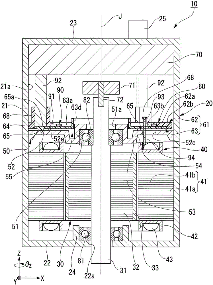
[0026] The XYZ coordinate system is appropriately represented in the drawings as a three-dimensional Cartesian coordinate system. In the XYZ coordinate system, the Z-axis direction is the same as figure 1 The axial parallel direction of the central axis J is shown. The X-axis direction is a direction orthogonal to the Z-axis direction, and is figure 1 in the left-right direction. The Y-axis direction is a direction orthogonal to both the X-axis di...


PUM


Abstract

A motor may include a rotor including a shaft; a stator arranged radially outside of the rotor; a bearing arranged on an upper side of the stator; a tubular housing; a bearing holder arranged on the upper side of the stator; and a busbar unit arranged on an upper side of the bearing holder. The rotor may include a rotor magnet fixed to the shaft. The stator may include an annular core back; teeth arranged to extend radially inward from the core back; and coils wound around the teeth. The housing may include a housing inner circumferential surface arranged to hold the stator. The bearing holder may be arranged to be in contact with the housing inner circumferential surface. The busbar unit may be arranged to be in contact with the housing inner circumferential surface.

Description

technical field [0001] The invention relates to a motor. Background technique [0002] Conventionally, some motors have a bus bar unit (for example, JP-A-2015-37331). The bus bar unit is attached to the stator core, for example. [0003] Among the motors, there is also a motor in which a bus bar unit, a bearing holder, and a stator are arranged in this order in the axial direction. In such motors, there is a bearing cage between the bus bar unit and the stator. Therefore, the bus bar unit cannot be attached to the stator core, and thus the bus bar unit cannot be positioned relative to the stator. Therefore, it is difficult to accurately position the bus bar unit with respect to the stator, and there is a possibility that the relative positional accuracy of the bus bar unit with respect to the stator may decrease. Contents of the invention [0004] In view of the above problems, an object of one embodiment of the present invention is to provide a motor having a structur...

Claims


Application Information

Patent Timeline
IPC IPC(8): H02K1/14H02K1/16H02K13/00H02K5/16H02K11/215
CPCH02K1/146H02K1/165H02K5/161H02K13/00H02K11/215H02K3/522H02K7/083H02K11/33H02K5/06H02K5/22H02K11/00H02K5/16H02K5/225
Inventor 新子刚央山下佳明河本达郎吉田雄策伊贺知辉
Owner NIPPON DENSAN CORP
Why Eureka
Try Eureka