Fan with active magnetic bearing

a technology of active magnetic bearings and fans, applied in the direction of bearings, shafts, dynamo-electric machines, etc., can solve the problem of prolonging the service li

Inactive Publication Date: 2008-03-27
EBM PAPST ST GEORGEN & -
View PDF22 Cites 29 Cited by
  • Summary
  • Abstract
  • Description
  • Claims
  • Application Information

AI Technical Summary

Benefits of technology

[0007]It is an object of the invention to make available a novel fan with magnetic bearings offering a high level of stability and reliability.
[0008]According to the present invention, this object is achieved by using a plurality of passive magnetic bearings to journal the rotor shaft within the stator, using an inner surface of a fan wheel to define a cylindrical air gap, and providing a plunger coil which extends into this air gap so that, upon axial displacement of the shaft with respect to the stator, the location of the plunger coil, with respect to the air gap, changes. A flux sensor, which detects the resulting change in flux, then produces a signal which can be used to actively control an axial magnetic bearing. This makes possible a compact and mechanically robust design, since a fan in any case requires a fan wheel that is driven by the rotor of the electronically commutated motor. In the context of the invention, the space inside the fan wheel is used to create a cylindrical air gap.
[0009]In the latter, an approximately radially extending magnetic field is generated, in which is located a plunger coil that is mechanically connected to the stator. As a function of the current in the plunger coil, the axial location or elevation of the fan wheel, and thus of the rotor relative to the stator, can be actively controlled, thereby yielding an actively controlled magnetic axial bearing having a simple structure. This minimizes friction and noise during operation, and lengthens the service life. It is possible, in this context, to maintain a low current through the plunger coil and thereby to reduce any negative influence on fan efficiency.
[0010]It is possible in this fashion to ensure friction-free, non-contact running of the rotor for fans in any mounting orientation (horizontal, vertical, etc.). Because the fan wheel levitates freely, the service life of the fan is increased and its noise output is reduced. An arrangement of this kind can also absorb the dead weight of the rotor as well as other forces acting in the axial direction, e.g. flow forces, electromagnetic forces, vibration forces, shock forces. This will also become clear from the description that follows. The elimination of bearing friction can furthermore improve efficiency.

Problems solved by technology

This minimizes friction and noise during operation, and lengthens the service life.

Method used


Image

  • Fan with active magnetic bearing
  • Fan with active magnetic bearing
  • Fan with active magnetic bearing

Examples


Embodiment Construction

[0038]In the description that follows, identical or identically-functioning parts are labeled with the same reference characters, and are usually described only once. Spatial terms such as “upper,”“lower,”“left,”“right” refer to the respective Figure.

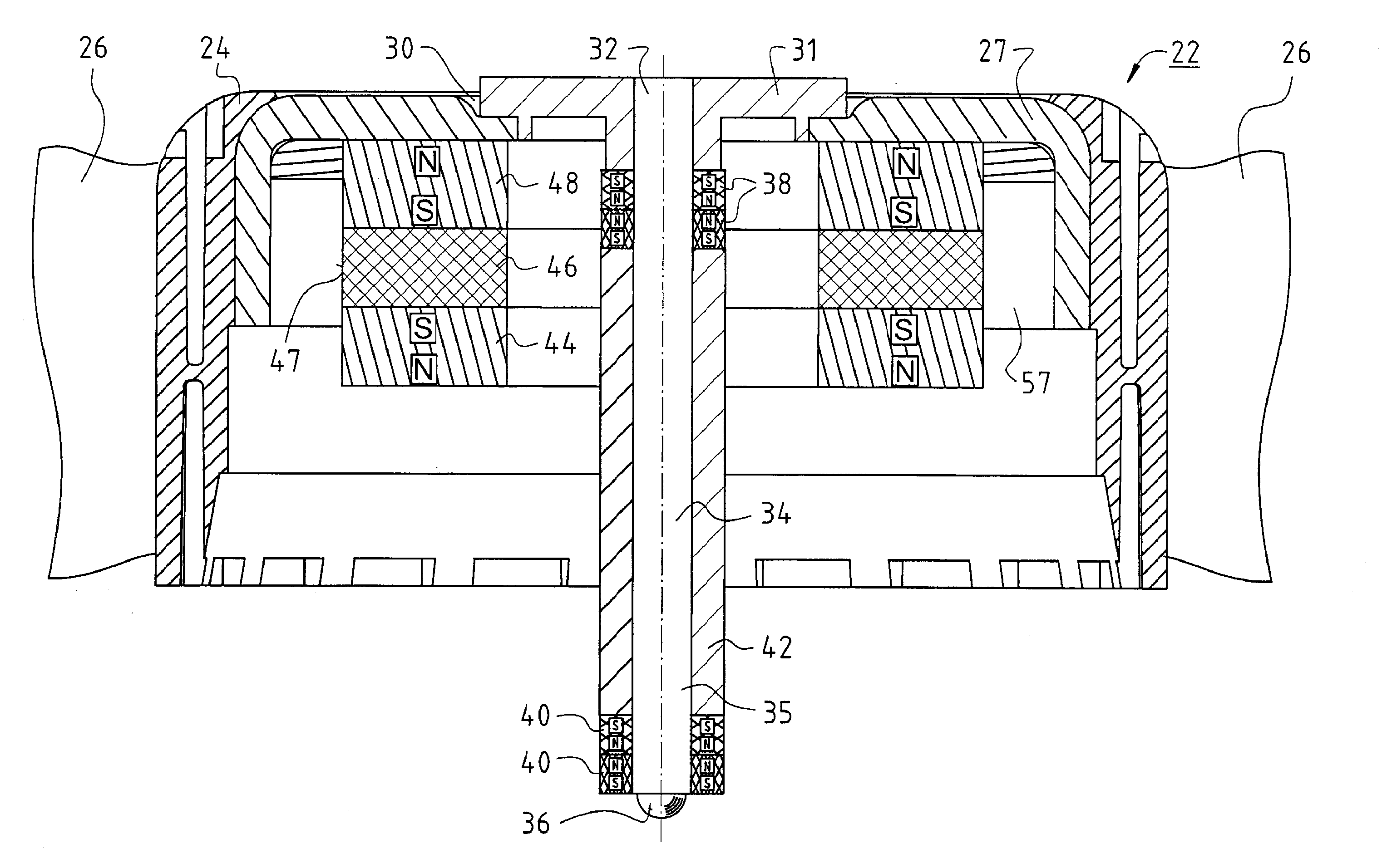
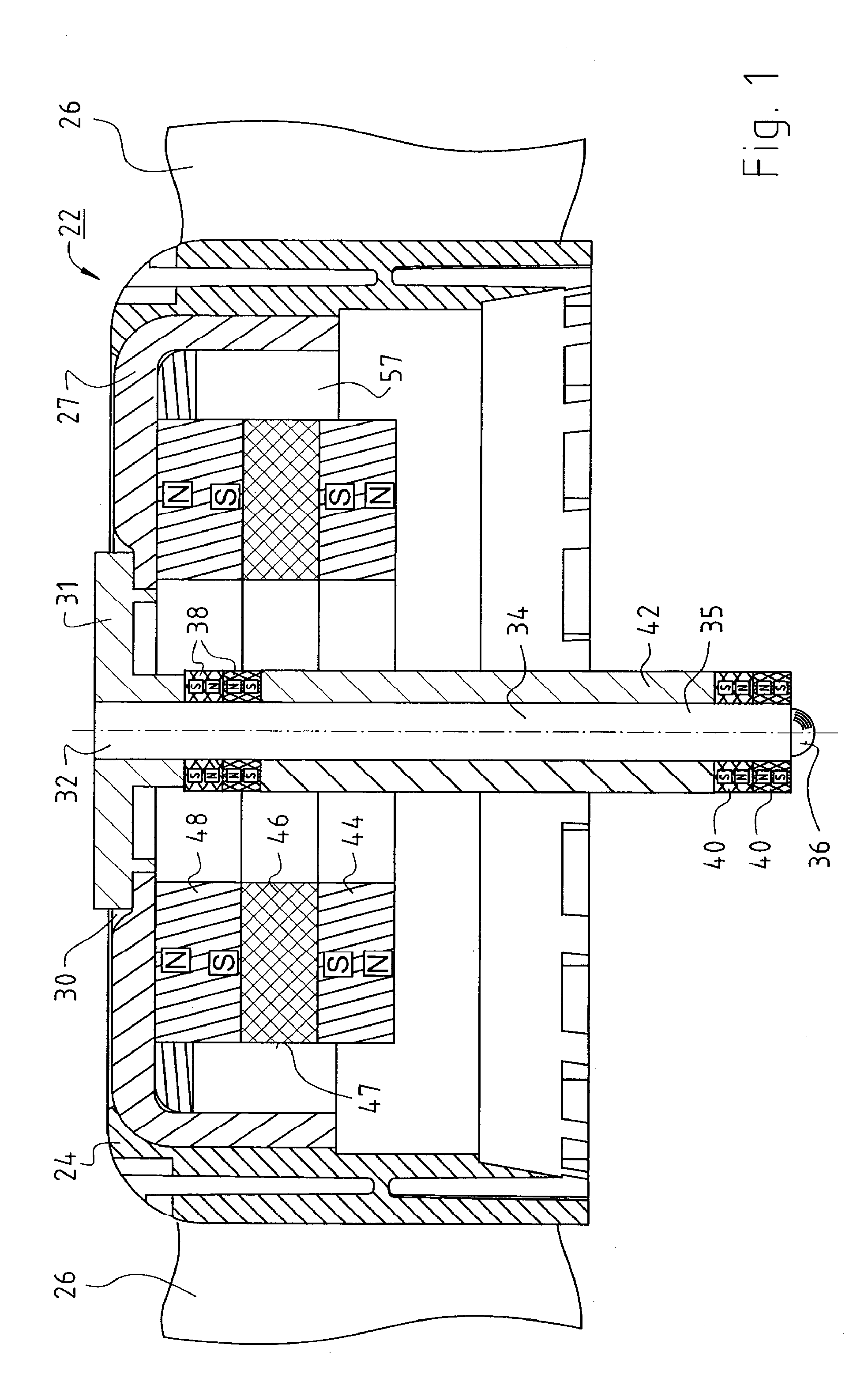
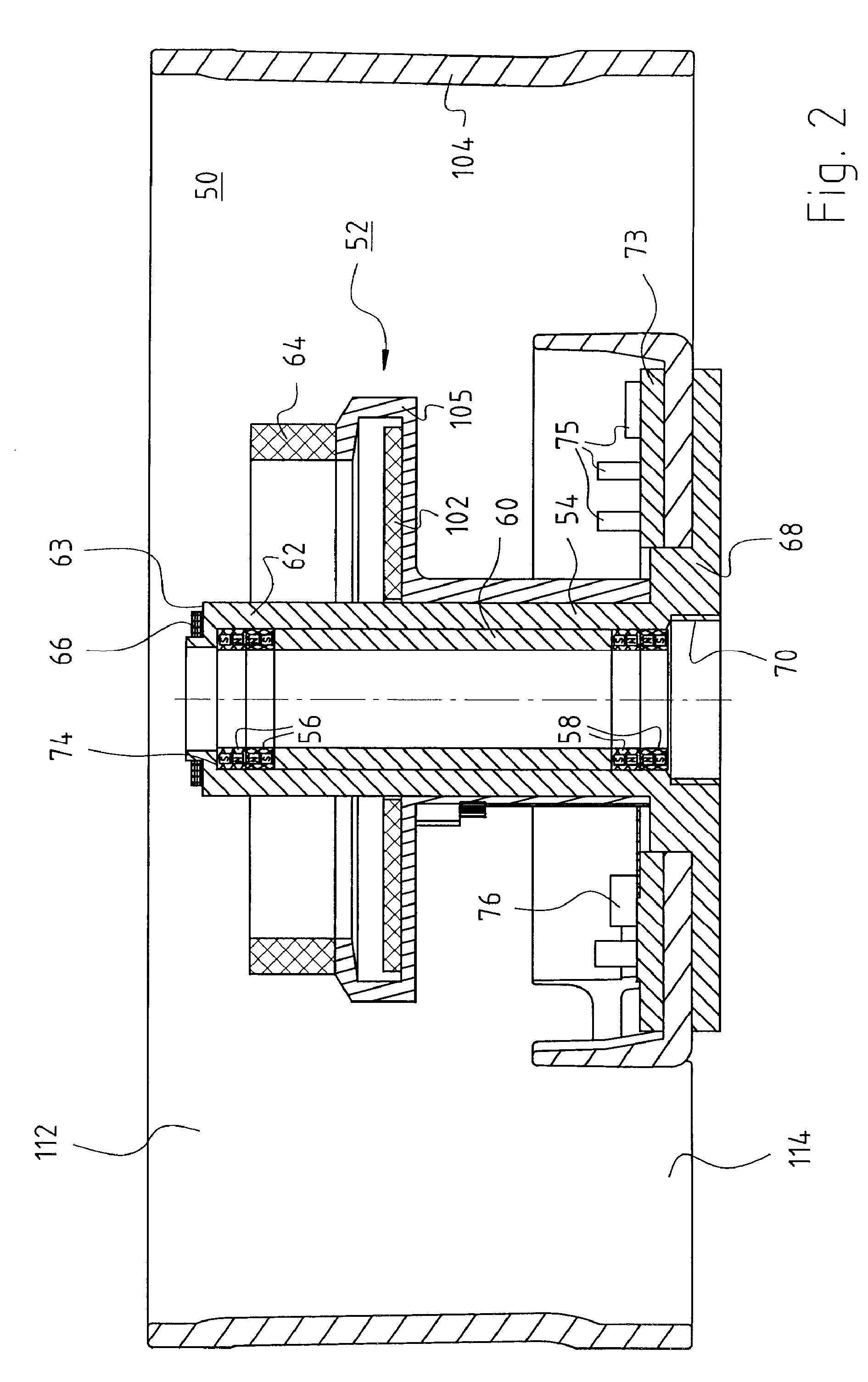
[0039]FIG. 1 shows rotor 22 of a fan 100. Rotor 22 has a rotor cup 24 having a base 30 in which an upper shaft end 32 of a rotor shaft 34 is mounted in an aluminum hub 31. The lower end of rotor shaft 34 is labeled 35. Aluminum hub 31 belongs to an eddy current sensor 33 (FIG. 7, FIG. 8) to which a sensor coil 66 (FIG. 2) also belongs. It is supplied with a high-frequency current 230 and consequently generates a high-frequency magnetic field, e.g. at a frequency of 1 MHz. Although theoretically a frequency in the range between 10 KHZ and 100 MHz could be used, the former frequency would make the controller response undesirably slow, and the latter frequency would make parasitic capacitance a problem. Upon a change in distance d (FIG. 7)...


PUM


Abstract

A fan (100) has an electronically commutated drive motor (ECM 52) with a stator (50) connected to a bearing tube (54) and a rotor (22) on a shaft (34). The shaft (34) is journaled in the tube (54) using passive radial magnetic bearings (16, 18) to minimize friction and wear, is axially displaceable with respect to the tube (54), and is drivingly connected to a rotor magnet (44) forming a first magnetic yoke (46). A second magnetic yoke (27) is connected to the shaft (34), and has an inner surface (59) defining a substantially cylindrical air gap (57) through which, during operation, a radial magnetic flux (55′) extends. A plunger coil (64) extends into the air gap (57) and is mechanically connected to the tube (54) so that, upon axial displacement of the plunger coil (64), the position of the shaft (34) with respect to the tube (54) changes.

Description

CROSS-REFERENCE[0001]his application claims priority of German application DE 10 2006 046 434.6 filed 22 Sep. 2006, the content of which is hereby incorporated by reference.FIELD OF THE INVENTION[0002]The present invention relates to a fan having an electronically commutated drive motor for driving fan blades. A drive motor of this kind has a stator and has a rotor equipped with a shaft, and its shaft is journaled within the stator.BACKGROUND[0003]Fans today are usually driven by electronically commutated motors. A bearing system for the fan wheel without mechanical bearings is desirable in such motors, principally for reasons of service life but also because of bearing noise. This applies in particular to fast-running fans such as those used, for example, to ventilate computer servers.[0004]Arrangements having permanent magnets are known for journaling without mechanical bearings. This is also referred to as a “non-contact bearing system” or as “magnetically journaled drive systems...

Claims


Application Information

Patent Timeline
Patent Type & Authority Applications(United States)
IPC IPC(8): H02K7/09G05B19/29H02K7/14G05D3/12
CPCF04D29/058F04D25/0653F16C32/0478F16C2380/26
Inventor JUNGMAYR, GERALDAMRHEIN, WOLFGANG
Owner EBM PAPST ST GEORGEN & -
Why Eureka
Try Eureka