Automatic pitch adjustment machine

a pitch adjustment machine and automatic technology, applied in the direction of conveyor parts, machine supports, stands/trestles, etc., can solve the problems of inconvenient and inaccurate operation, increased manpower consumption, and inconvenient operation

Inactive Publication Date: 2019-01-22
HUANG HSIN PO
View PDF8 Cites 1 Cited by
  • Summary
  • Abstract
  • Description
  • Claims
  • Application Information

AI Technical Summary

Benefits of technology

[0004]The main objective of the present invention is to provide an automatic pitch adjustment machine that can automatically deploy the components to be separated at intervals of a specific distance.

Problems solved by technology

The manually operated way consumes more manpower and also is inconvenient and inaccurate.

Method used


Image

  • Automatic pitch adjustment machine
  • Automatic pitch adjustment machine
  • Automatic pitch adjustment machine

Examples


Embodiment Construction

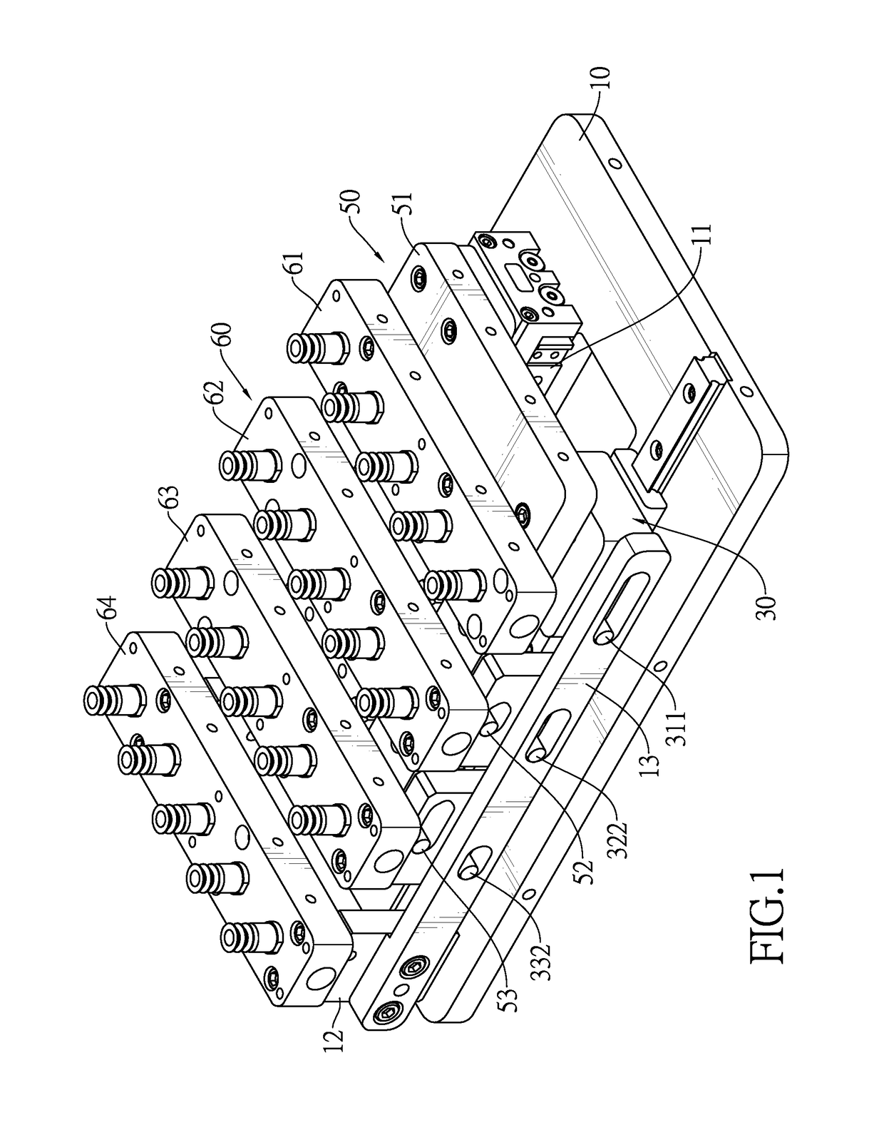
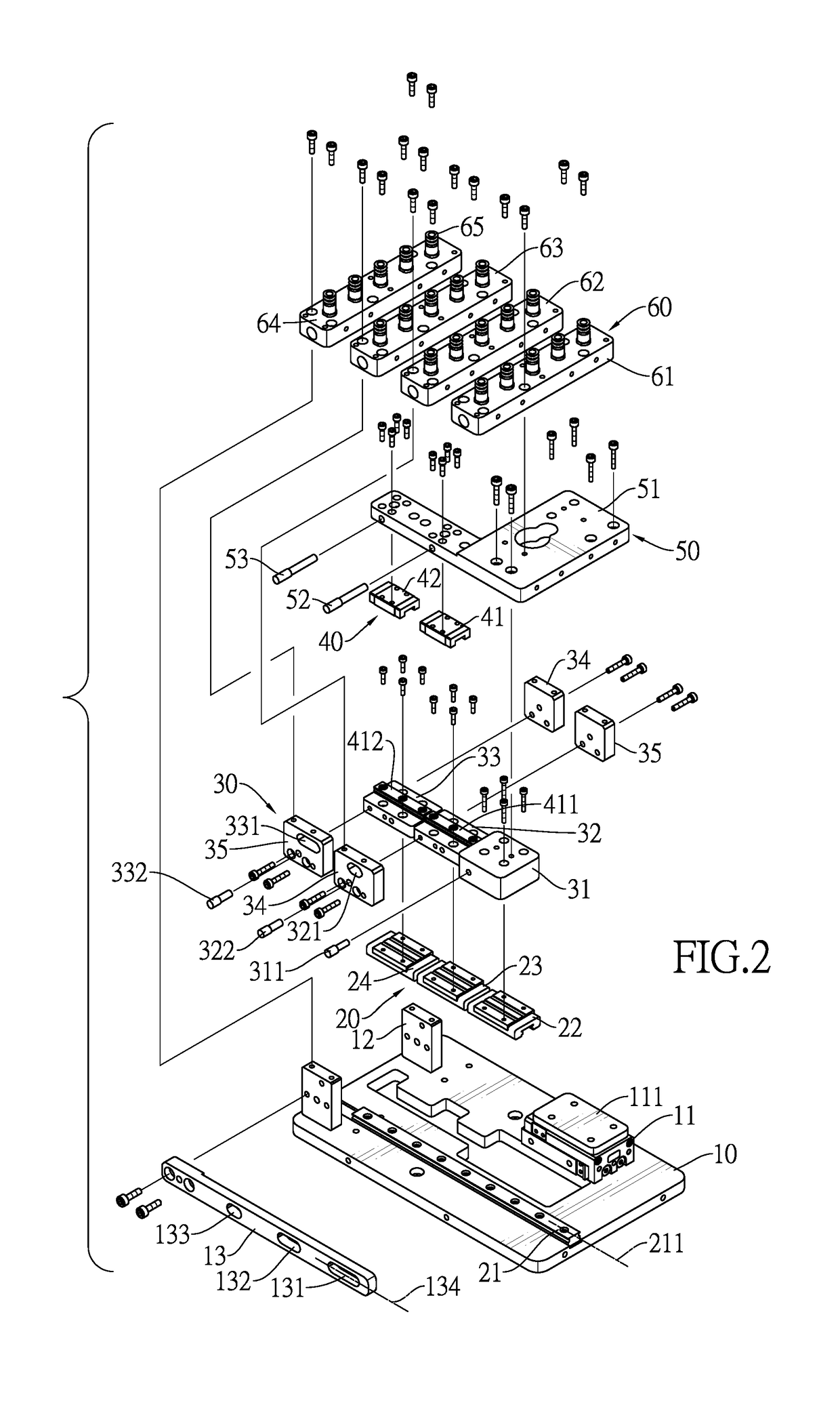
[0014]With reference to FIGS. 1 and 2, an automatic pitch adjustment machine in accordance with the present invention comprises a base board 10, a first slide rail set 20, a transfer set 30, a second slide rail set 40, a cylinder adapter plate 50, and a material carrier set 60.

[0015]The base board 10 has a cylinder set 11, at least one fixed pillar 12, and a positioning board 13. The cylinder set 11 is mounted on a top surface of the base board 10 and has a sliding board 111. The sliding board 111 is movable and has a moving direction. The sliding board 111 is driven by fluid. For example, the cylinder set 11 is a pneumatic cylinder. The sliding board 111 can be reciprocately driven by the pneumatic cylinder. The sliding board 111 may be conventional and the detailed description thereof is omitted.

[0016]The at least one fixed pillar 12 is mounted on the top surface of the base board 10 and is away from the cylinder set 11. Preferably, the base board 10 has two fixed pillars 12. The ...


PUM


Abstract

An automatic pitch adjustment machine has a base board, a first slide rail set, a transfer set, a second slide rail set, a cylinder adapter plate, and a material carrier set. The the first slide rail set is mounted on the top surface of the base board. The transfer set has multiple transfer blocks, and each one of the transfer blocks is fixed to a respective lower sliding block of the second slide rail set. The second slide rail set has multiple short rails and multiple upper sliding blocks. The cylinder adapter plate has a driving plate and multiple driving pillars. The material carrier set has multiple material fixing boards, and the multiple material fixing boards are spaced at intervals.

Description

BACKGROUND OF THE INVENTION1. Field of the Invention[0001]The invention relates to a pitch adjustment machine, and more particularly to an automatic pitch adjustment machine which can automatically separate components at intervals of a specific distance during a manufacturing process.2. Description of Related Art[0002]During processes for manufacturing products in a factory, especially for products of a small volume, the products would be transported from one working station to a next working station. These small products or materials are transported in different quantities. Due to the configurations of apparatuses or the manufacturing space, the products or materials are moved from one working station to another. The distance between two adjacent products or materials should be adjusted in order to make the process smooth.[0003]In the prior art, the means for changing the distance between the multiple products or materials in the production process are usually manually operated. Th...

Claims


Application Information

Patent Timeline
Patent Type & Authority Patents(United States)
IPC IPC(8): B65G47/28F16M11/20
CPCB65G47/28F16M11/2092B65G47/918
Inventor HUANG, HSIN-PO
Owner HUANG HSIN PO
Why Eureka
Try Eureka