Firearm support

a technology for supporting and firing guns, applied in the direction of butts, weapons, weapon components, etc., can solve the problems of reducing the effectiveness of typical vertical supports, affecting the safety of shooters, and reducing the degree of stress, so as to achieve wide head, wide base, and wide firing angle

Active Publication Date: 2019-01-29
RENTERIA JAMES
View PDF24 Cites 5 Cited by
  • Summary
  • Abstract
  • Description
  • Claims
  • Application Information

AI Technical Summary

Benefits of technology

[0007]The firearm support of the present invention addresses the aforementioned needs in the art by providing a gun handle that attaches to the lower surface of a rifle, such as to the lower rail, and is substantially more versatile in steadying the rifle during shot prosecution relative to a standard monopod type of gun handle. Specifically, the firearm support has a relatively wide base allowing the rifle to be positioned in or repositioned to a relatively wider degree of firing angles while adding the requisite support needed for fat initial shots and follow on shots. The firearm support of the present invention has a relatively wide head that allows a shooter to cant the firearm and provides a stable platform for shooting from adverse positions and angles. The firearm support forces pressure downward and forward into an obstacle or barricade providing a stable firing position for the firearm even if firing one handed which is especially useful if the shooter is wounded, allowing the wounded shooter to use the device by leveraging the shooter's body and the device against an obstacle, barricade or piece of cover. The firearm support is simple in design and construction, being produced using standard manufacturing techniques, and is lightweight, easy to install and remove, and permits a user to use his or her favorite grips and rails on the firearm as desired. The offset and geometry of the firearm support gives the shooter proper muzzle sight relationship when shooting around objects by forcing the barrel away from the object helping prevent firing into the object during high stress firing. The firearm support is configured to stabilize the firearm when resting the present invention on a linear object, such as a railing or a non-flat object such as a pipe. The firearm support is configured to function as a stand in order to support the firearm to which the device is attached when the firearm is resting in a generally vertical position against a flat surface. The firearm support has a relatively large cross-guard section that helps steady the firearm when the present invention is jammed up against an object, such as a wall or window sill, while allowing pivot support when swinging the firearm to one side or the other for shooting. This area also serves as a thumb support when using the device as a grip. The firearm support effectively functions as a grip stop, either alone or in conjunction with other grip stops or attachments. In close combat, the firearm support acts as an effective striking surface when bringing the firearm bearing the device downwardly onto an adversary.

Problems solved by technology

However, in an active shooting environment, such as in combat or in a police encounter, the stress level is extremely high with the shooter's adrenaline gushing.
In such events getting a good shot off in order to eliminate the active threat may mean the difference between life and death for the shooter or others depending on the shooter.
In these and other firing situations, the typical vertical support often proves less than completely effective, if at all, in helping dispatch the best possible shots at the threat present.

Method used


Image

  • Firearm support
  • Firearm support
  • Firearm support

Examples


Embodiment Construction

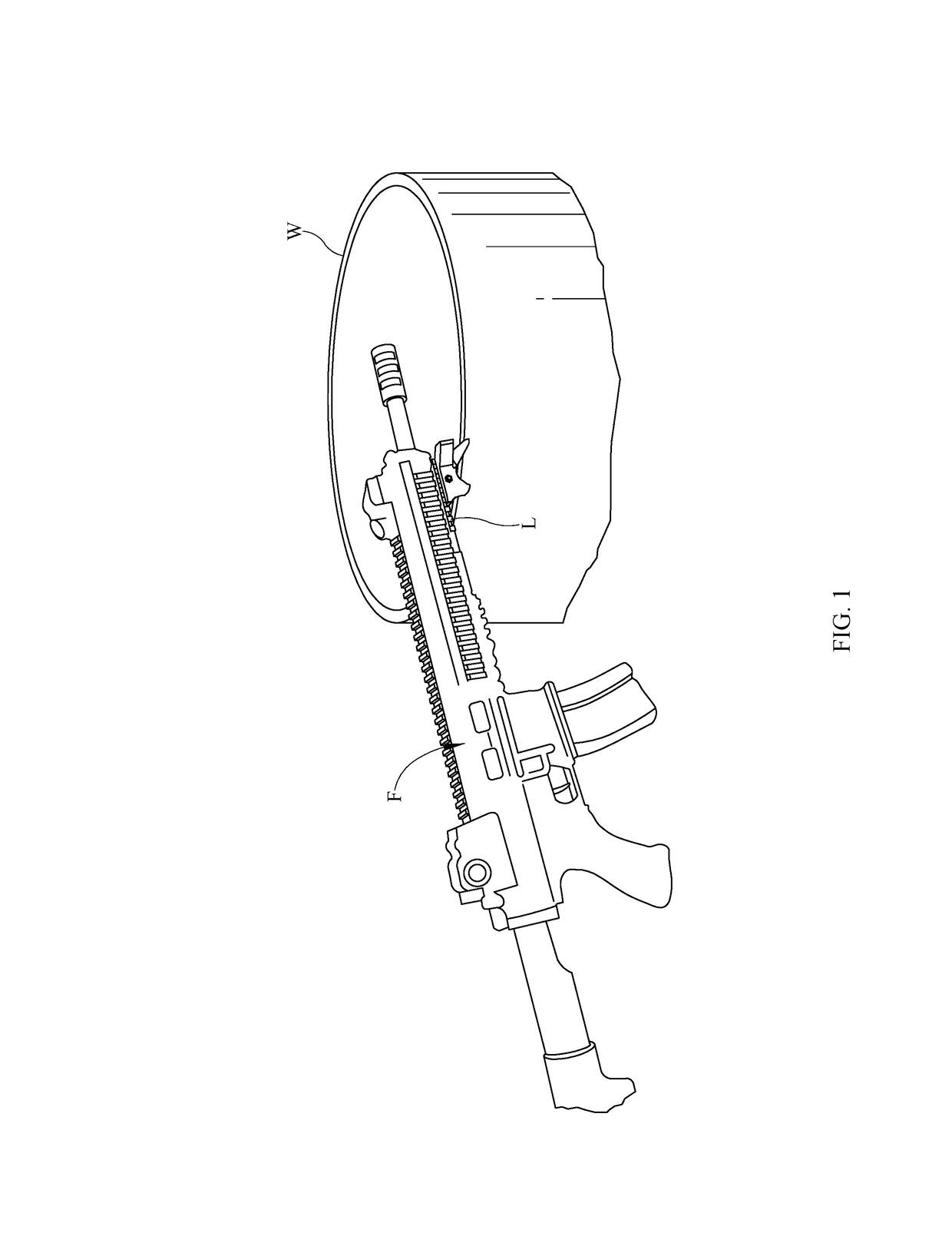
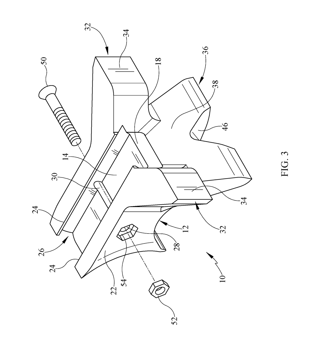
[0019]Referring now to the drawings, it is seen that the firearm support of the present invention, generally denoted by reference numeral 10, is comprised of a body member 12 that has a top 14, a bottom 16, a front 18, a rear 20, a pair of sides 22, the firearm support 10 essentially symmetrical about a midline passing from the front 18 to the rear 20 between the pair of sides 22.

[0020]As seen, a pair of spaced apart rails 24 upwardly extends upwardly from the top 14 of the body member 12 one each at either side 22 of the body member 12. The pair of rails 24 along with the surface of the top 14 form a channel 26 that is shaped and dimensioned to receive a lower rail L of a firearm F in the usual way. As seen, corresponding openings 28 are provided, one on each respective rail 24 while a bolt groove 30 extends between the two openings 28 and within the surface of the top 14.

[0021]As seen, a pair of extensions 32 extends outwardly, one extension 32 from each side 22 of the body member...


PUM


Abstract

A firearm support attaches to a lower surface of a firearm and helps steady the firearm during shooting from almost any firing position. The support has a body member that has a firearm lower railing receiving channel on its upper surface and a downwardly and forwardly curving claw extending from the lower surface at the front. The claw has a rounded edge and a centrally disposed wedge opening. The lower surface of the body member is also curved as is the rear surface. A pair of extendions extends outwardly, one from each side of the body member just above the upper end of the claw and each has a forward facing surface that is flat.

Description

BACKGROUND OF THE INVENTION1. Field of the Invention[0001]The present invention relates to a support or vertical grip that extends downwardly from the lower rail of a rifle and assists the shooter in supporting the rifle during various firing modes of the rifle.2. Background of the Prior Art[0002]When shooting a rifle at a shooting range, such as the military's M-16 or the civilian counterpart, the AR-15, many shooters take one of a handful of positions, including the standing position, the sitting position, the kneeling position, or the prone position. In such positions, the shooter uses the non-trigger hand to support the rifle from underneath, typically by grasping the lower rail, and uses the opposing hand to fire the rifle. Some shooters may support the rifle on the bench top or a sandbag, for example, especially when in the sitting or prone position. When sighting a rifle in, shooters may use an appropriate support in order to keep the rifle absolutely steady during shot firin...

Claims


Application Information

Patent Timeline
Patent Type & Authority Patents(United States)
IPC IPC(8): F41A23/02
CPCF41A23/02F41C23/16
Inventor RENTERIA, JAMES
Owner RENTERIA JAMES
Why Eureka
Try Eureka