Knife sharpener

a knife and sharpener technology, applied in the field of knife sharpeners, can solve the problems of invariability of design of knife sharpeners, people's dislike of use, and high cost and time consumption, and achieve the effect of producing with little economic cos

Inactive Publication Date: 2007-06-12
FLUGEL CSS
View PDF15 Cites 7 Cited by
  • Summary
  • Abstract
  • Description
  • Claims
  • Application Information

AI Technical Summary

Benefits of technology

[0006]the present invention provides a knife sharpener that on the one hand can be used for sharpening while being mounted on a substrate without the user having to hold on to it. Beyond that, regarding external styling and design, the knife sharpener should be quite variable and, regarding production and assembly, producible with little economic expense.
[0008]In accordance with the present invention, the knife sharpener is characterized by the casing being designed with a wide base compared to the grinding tool, and a simple grinding tool retainer. This can be, for example, a plastic injection-molded part, which can also be made of a single piece.
[0010]The incorporation of the grinding element in the surface opposite the base takes place in such a way that it is in the middle in relation to the comparatively wide base. In this way, it is guaranteed that moving a knife beyond the grinding element surface will not tip the knife sharpener.
[0012]Receivers can also be constructed in the housing, for example, boreholes or such, in which the ends of the grinding element can be inserted. Advantageously, mounting the grinding element will occur in a way that allows the grinding element to be at least slightly movable. In this case, the grinding element will be supported from below by spring devices. The advantage of this is that a knife placed on the grinding element will absorb some of the pressure. On the other hand, the grinding element is always held in an upper position. This results in flexible adaptation, so that the grinding element always lies against, for example, concave or convex cutting edge shapes.
[0015]A more expensive design might feature two, three or more grinding elements arranged parallel to one another, which would practically provide one grinding surface. In this case the base should not be designed too wide opposite to the surface of the grinding element, since the tilting effect is absorbed by the surface. Even rectangular casings are appropriate in this case. This embodiment with its broad base and a grinding element is inventive and capable of protection in dependence independently from the previously described simpler design. It is a knife sharpener, in which the surface of the grinding element and the base are similar to the simpler design, the casing therefore having a cuboid shape. Since there are two, three, or more parallel grinding elements, the pressure is absorbed by a greater surface, and the knife sharpener is prevented from tipping over.
[0018]During the sharpening process, the knife is passed across the grinding element with one hand, with the aid of the second hand for better guidance with bigger knives, at an angle of, for example, 20° from both sides. If necessary, the grinding element can be rotated manually after the sharpening, so that it is not worn out on one side, and its entire circumference can be used.

Problems solved by technology

The disadvantage with previously known knife sharpeners is that people do not like to use them since they are afraid of injuring themselves.
Also, people generally object to sharpeners due to its weapon- or tool-like nature.
Furthermore, knife sharpeners are quite invariable regarding design, very expensive and time-consuming as far as production, assembly and operation are concerned.

Method used


Image

  • Knife sharpener
  • Knife sharpener
  • Knife sharpener

Examples


Embodiment Construction

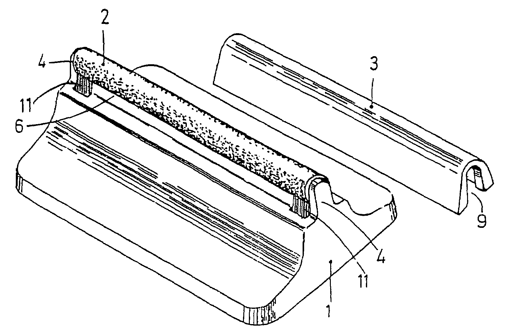
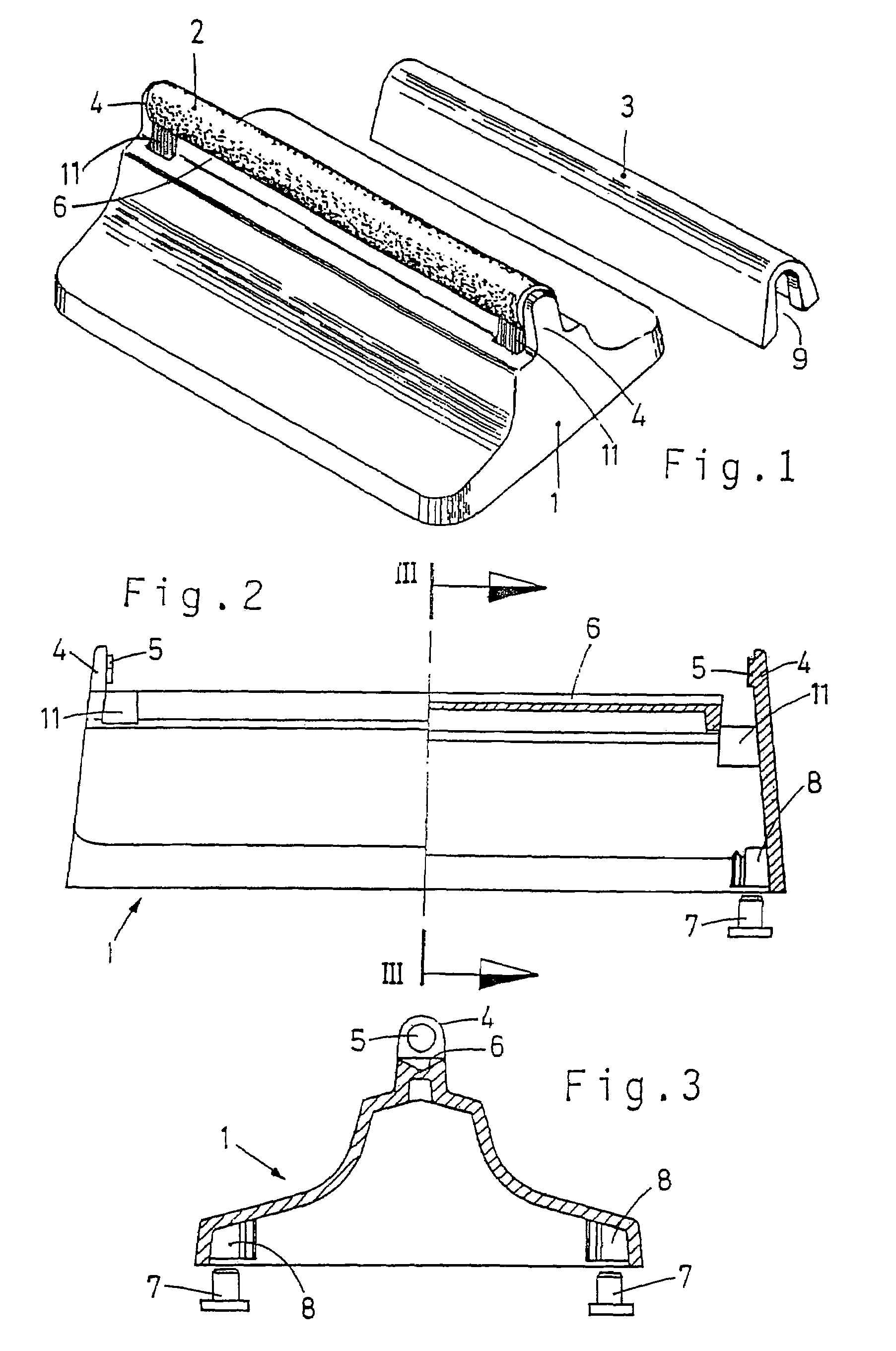
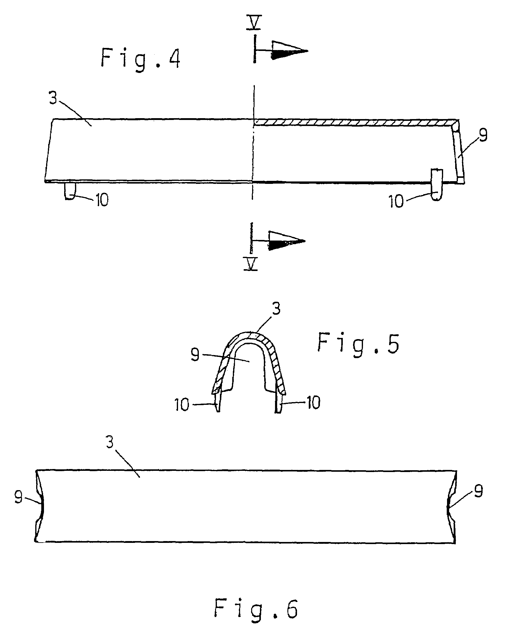
[0033]The knife sharpener represented consists primarily of an injection molded plastic housing 1 made in one piece with a large base, a ceramic grinding element 2, and a protective cover 3, which is seen taken off in FIG. 1, showing the knife sharpener on a table or other work bench ready to be used.

[0034]FIG. 2 shows a half longitudinal section of the housing 1 by itself from the front. There are two arms 4 with one hole on both sides of the housing, in between which the grinding element 2, as seen in FIG. 1, is loosely inserted. Grinding element 2 is a hollow ceramic cylinder, whereby short studs 5 of the supporting arms 4 are inserted into the ends of the same, which are somewhat elastically pliable, in a way that grinding element 2 rests against supporting arms 4 with some friction, but can be turned by hand, if required, in order to use another area of the grinding element's circumference for sharpening household knives or such, if the previously used area of the circumference...


PUM

PropertyMeasurementUnit
angleaaaaaaaaaa
heightaaaaaaaaaa
heightaaaaaaaaaa

Abstract

The invention concerns a knife sharpener for household knives or the like. In order to design a knife sharpener, which, one the one hand, can be used for sharpening and sits solidly on a surface without it having to be held, and which, on the other hand, is producible with little economic cost regarding production and assembly, the invention proposes a knife sharpener with a housing, which has a surface designed to be a base, and at least one longitudinal, cylindrical grinding element made from ceramics, at least part of the surface of which is arranged on the surface of the housing, whereas the base is designed at a right angle to a longitudinal line of the grinding element and the grinding element is positioned in the middle in relation to a projection of the base.

Description

TECHNICAL FIELD OF INVENTION[0001]The invention concerns a knife sharpener for kitchen knives or such.BRIEF DESCRIPTION OF RELATED ART[0002]There are knife sharpeners of many types and modes of operation. For example, there are knife sharpeners which correspond to the classical sharpening steel. These sharpeners consist of a handle and a grinding rod made of steel or ceramics. The handle can be provided with a hand guard so that untrained users are protected from injuries.[0003]There are also knife sharpeners that are fixed as floor-mounted appliances on a work bench or such. The user generally has to hold it with one hand while sharpening the blade of the knife on a grinding tool made, for example, of steel or ceramic materials, applying more or less pressure.[0004]The disadvantage with previously known knife sharpeners is that people do not like to use them since they are afraid of injuring themselves. Also, people generally object to sharpeners due to its weapon- or tool-like nat...

Claims


Application Information

Patent Timeline
Patent Type & Authority Patents(United States)
IPC IPC(8): B24B19/00B24B3/36B24B3/54B24D15/06B24D15/08
CPCB24D15/065B24D15/08
Inventor FIERUS, UDOFIERUS, GERD
Owner FLUGEL CSS
Why Eureka
Try Eureka