Wafer shipper

a shipper and substrate technology, applied in the direction of packaging, electrical equipment, other accessories, etc., can solve the problems of increased stress, unsatisfactory use of the case shipper with the thinner wafer, and substantially more fragile and prone to physical damage than a standard wafer, so as to reduce the likelihood of the wafer being disposed, and enhance the resistance of the rotation of the wafer engagement pad

Active Publication Date: 2015-03-12
ENTEGRIS INC
View PDF6 Cites 6 Cited by
  • Summary
  • Abstract
  • Description
  • Claims
  • Application Information

AI Technical Summary

Benefits of technology

[0015]A feature and advantage of embodiments of the present invention are cantilevered elongate fingers that have a proximal portion, a narrowed neck or mid portion, and a flared distal portion. The width, measured in the direction parallel to the axis of the stack of wafers, of the fingers is narrowest at the neck portion and widest at the proximal portion adjacent the rail to which it connects. The flared distal portion defining a wafer engaging pad with a distal tip of the pad the furthermost forward, that is towards the wafer engagement direction, of any portion of the finger. The depth of the finger, measured in a direction perpendicular to the axis of the stack of wafers, being the greatest at the distal tip. The width of the wafer engagement pad, measured in the direction parallel to the axis of the stack of wafers, being the greatest at the distal end. In embodiments of the invention the shape of the elongate fingers, when viewed from the front or back, can be said to be bow tie shaped.
[0016]A feature and advantage of embodiments of the present invention are cantilevered elongate fingers that have a proximal portion, a narrowed neck or mid portion, and a flared distal portion. The fingers being arranged in a row for engaging the stack of wafers, each of the flared distal portions being arranged to alternate in the flare direction; that is one finger has the distal portion extending and flaring to a right side, the sequential next has its distal portion extending towards and flaring to a left side, the sequential next to the right, and so on.
[0017]Another feature and advantage of embodiments of the present invention is fingers having a pad that flares outwardly towards a distal end of pad. Flared portion of a specific finger occupies the space between adjacent narrowed portions of the fingers adjacent to the specific finger, and therefore reduces cross-slotting by reducing the likelihood of wafers being disposed in the space between pads. Wafers are instead guided into the wafer slots on pads to be properly seated.
[0018]A feature and advantage of embodiments of the invention is that the proximal portion of each cantilevered wafer engagement finger comprises two legs that provide an enhanced resis

Problems solved by technology

Thin wafers present unique design considerations, and cassette style shippers are unsatisfactory in several respects for use with the thinner wafers.
Another characteristic of thin wafers is that they can be substantially more fragile and prone to physical damage than a standard wafer.
A conventional wafer carrier having limited support f

Method used


Image

  • Wafer shipper
  • Wafer shipper
  • Wafer shipper

Examples


Embodiment Construction

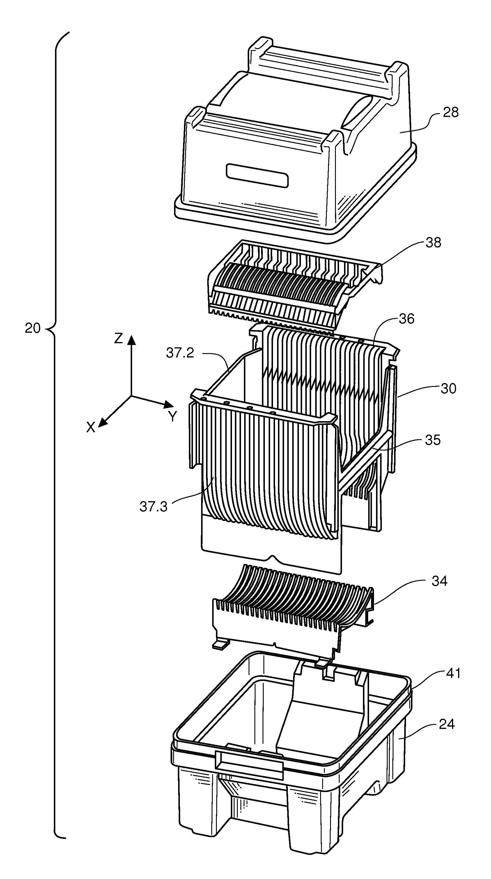
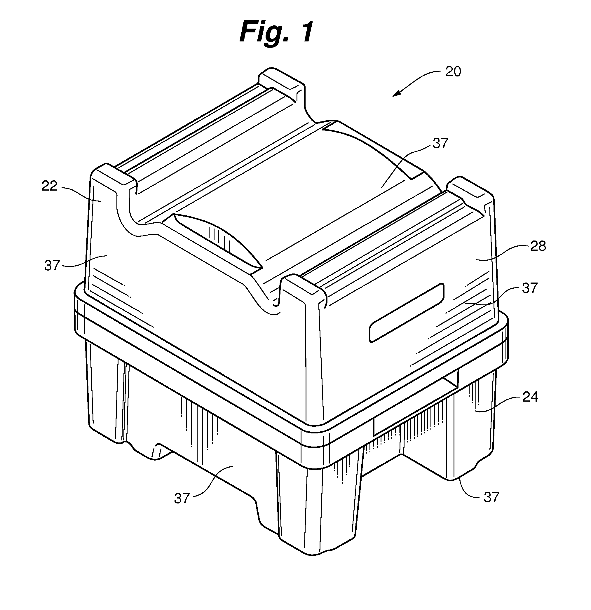
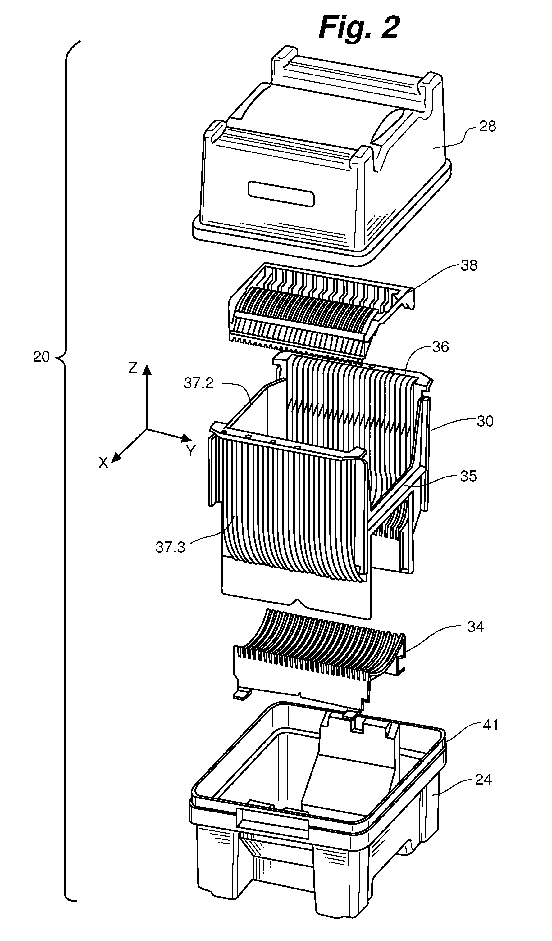
[0038]Referring to FIGS. 1, 2, and 3, a wafer shipper 20 according to an embodiment of the invention is illustrated and is comprised generally of a container portion 22 comprising a base portion 24 and a top cover portion 28, a cassette 30, a lower cushion 34, and an upper cushion 38. The base portion and top cover portions comprise pluralities of walls 37. Consistent with normal convention, the wafers are inserted and removed in the z direction, and the y direction is parallel to the axis a of the stack 39 of wafers W, one of which is illustrated in FIG. 3. The slots are aligned in the x direction. As can be seen in FIG. 3, lower cushion 34 and cassette 30, known as an H-bar carrier or cassette, are positioned in base portion 24 to receive wafers W. The H-bar carrier has an H-bar 35, teeth 36, an open bottom 37, end wall 37.2, and side walls 37.3. Upper cushion 38 can be mounted in cover portion 28, and engages the wafers W when the cover portion 28 is positioned on the base portio...


PUM


Abstract

A wafer container for holding a spaced stack of thin wafers, comprising an H-bar carrier, a base portion for receiving same, a base wafer cushion attached at the bottom wall positioned below the H-bar carrier, the cushion having a plurality of ribs defining slots each with a bottom wafer seating region having a curvature and a pair of ends, each of the ends having a flare whereby the seating region flares outwardly at the ends, a cover portion that connects with the base portion to form a closed interior. The cover portion having an uppermost wall a wafer cushion secured thereto. The cover wafer cushion having a row of wafer engaging finger portions, the finger portions Y shaped and having two legs extending from a support portion and alternatingly extending from opposing support portions, the finger portions may be S shaped with a wafer pad flared in two direction.

Description

FIELD OF THE INVENTION[0001]The present invention relates generally to containers for carrying substrates and semiconductor wafers, and the like. More particularly, the present invention relates to an improved wafer support mechanism in a wafer container useful for carrying a plurality of axially aligned thin mostly circular wafer substrates.BACKGROUND OF THE INVENTION[0002]For years, manufacturers have produced special containers for transporting and storing substrates and semiconductor wafers, and the like. Due to the delicate nature of the wafers and their extreme value, it is vital that they are properly protected throughout the transportation process. Since the handling of wafers is generally automated, it is necessary for wafers to be precisely positioned relative to the handling equipment for the robotic removal and insertion.[0003]In addition to protection from damage by breakage, cleanliness and contamination control is critical in shipping storing or processing semiconduct...

Claims


Application Information

Patent Timeline
IPC IPC(8): H01L21/673
CPCH01L21/67383H01L21/67369H01L21/67386
Inventor RASCHKE, RUSS V.GREGERSON, BARRYSTEFFENS, JASON TODD
Owner ENTEGRIS INC
Why Eureka
Try Eureka