Boiler system comprising an integrated economizer

a boiler system and boiler technology, applied in steam boilers, preheating, feed-water heaters, etc., can solve the problems of reducing the needed energy input, tempered by the cost, and the vast majority of boilers that require significant energy

Active Publication Date: 2019-02-05
SIMONEAU P I INC
View PDF15 Cites 4 Cited by
  • Summary
  • Abstract
  • Description
  • Claims
  • Application Information

AI Technical Summary

Benefits of technology

[0010]A boiler system in accordance with the principles of the present invention generally mitigates at least some of the shortcomings of prior art combination of boiler systems and economizers by comprising a fully integrated economizer.
[0020]Understandably, a boiler system with an integrated economizer in accordance with the principles of the present invention generally mitigates at least some shortcomings of prior art boiler systems. For instance, since the economizer is located at the top of the boiler, the combined boiler and economizer does not have a larger footprint compared to a regular boiler system without economizer. Furthermore, since the boiler system is installed with its integrated economizer, there are important transportation and installation costs savings. In addition, due to the total integration of the economizer with the boiler system, the boiler system generally has improved energy efficiency.
[0021]The present invention is particularly adapted for heating water and producing high-temperature steam. Feedwater enters first the economizer module before entering the furnace module. In addition, due to the complete integration of the economizer on the top of the boiler system, the boiler system can provide significant transportation and installation costs savings as boiler system and its economizer are transported and installed only once.

Problems solved by technology

Though many boiler designs are known in the art, it remains that the vast majority of these boilers requires significant amount of energy for generating the required heated fluid or steam.
However, the need for more energy efficient boilers is tempered by their costs.
This raises the temperature of the boiler feedwater, thus lowering the needed energy input, in turn reducing the firing rates to accomplish the rated boiler output.
However, economizers are generally standalone equipment, sold separately, which require labor and parts in order to be fitted to existing boiler systems.
The overall additional equipment is often bulky and requires a substantial amount of space.
In addition, most of the time, the additional equipment needs to be transported to the boiler site, which also raises the costs.
Moreover, the equipment is also often required by industries located in geographical regions wherein specialized or skilled labor is not readily available.

Method used


Image

  • Boiler system comprising an integrated economizer
  • Boiler system comprising an integrated economizer
  • Boiler system comprising an integrated economizer

Examples


Embodiment Construction

Boiler System

[0028]A novel boiler system comprising an integrated economizer will be described hereinafter. Although the invention is described in terms of specific illustrative embodiments, it is to be understood that the embodiments described herein are by way of example only and that the scope of the invention is not intended to be limited thereby.

[0029]Reference will be made herein after to FIGS. 1 to 4, in which:

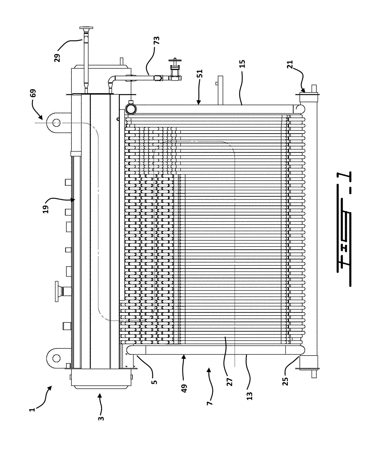
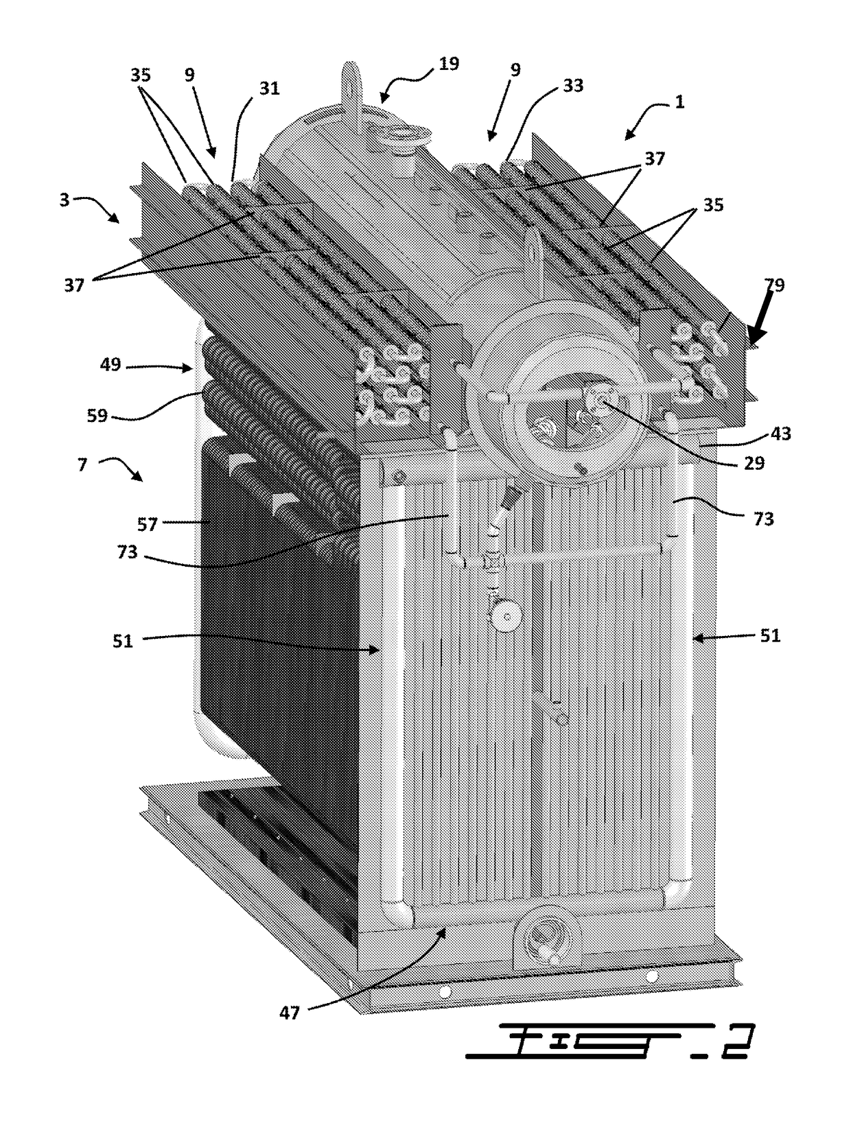
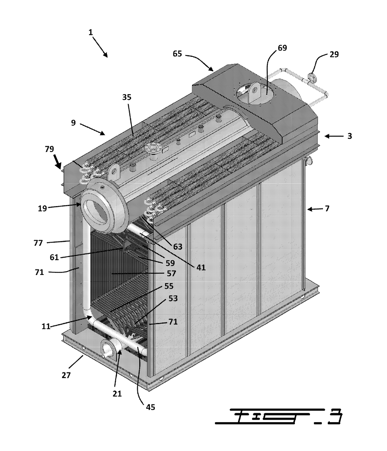
[0030]1 Boiler system

[0031]3 Economizer module

[0032]5 Top portion of the Furnace module

[0033]7 Furnace module

[0034]9 Pre-heating tube assembly

[0035]11 Combustion chamber

[0036]13 Front wall

[0037]15 Rear wall

[0038]19 Upper header or drum

[0039]21 Lower header

[0040]25 Bottom portion of the boiler system

[0041]27 Tubes of the furnace module

[0042]29 Inlet of the economizer module

[0043]31, 33 Tube sub-assemblies

[0044]35 Tubes of the sub-assemblies

[0045]37 Baffles

[0046]41, 43, 45, 47 Conduits of the furnace module

[0047]49, 51 Downcomers

[0048]53 First section of the furnace tubes...


PUM


Abstract

A boiler system and methods for heating a fluid are disclosed, in particular for heating water for producing steam. The boiler comprises an economizer module integrated on the top of a furnace, and is in communication with the furnace to receive heat and / or hot combustion gases therefrom. The economizer comprises tubes receiving the fluid, such as feedwater, to be pre-heated and providing it to the furnace comprising a combustion chamber producing heat and hot combustion gases. The fluid is pre-heated by circulating first through the pre-heating tube assembly of the economizer module before entering the furnace module where the fluid is further heated by the combustion chamber. Since the economizer is located on the furnace module, the boiler does not have a large footprint compared to a regular boiler system without an economizer. Due to the total integration of the economizer with the furnace, the boiler system has improved energy efficiency.

Description

CROSS-REFERENCE TO RELATED APPLICATIONS[0001]The present patent application claims the benefits of priority of U.S. Patent Application No. 62 / 011,238, entitled “Boiler System Comprising an Integrated Economizer”, and filed at the U.S. Patent Office on Jun. 12, 2014, the content of which is incorporated herein by reference.FIELD OF THE INVENTION[0002]The present invention generally relates to boiler systems, more particularly but not limited to flexible tube boiler systems, for heating a fluid, in particular but not limited to the heating of water to produce steam.BACKGROUND OF THE INVENTION[0003]The use of boilers and boiler systems is well known in the art and many different designs have been proposed such as for instance in U.S. Pat. No. 2,065,559 (Blodgett), U.S. Pat. No. 3,280,800 (Sullivan); U.S. Pat. No. 3,368,536 (Sullivan); U.S. Pat. No. 4,170,964 (Jehn et al.); or U.S. Pat. No. 4,342,286 (Pollock).[0004]Boilers are generally used for heating fluids such as water, glycol / wat...

Claims


Application Information

Patent Timeline
Patent Type & Authority Patents(United States)
IPC IPC(8): F22D1/02F22D1/06F22D1/20F22D1/10F22B21/34F22B21/04
CPCF22D1/02F22B21/04F22D1/20F22D1/06F22D1/10F22B21/346
Inventor GAUTHIER, REJEAN
Owner SIMONEAU P I INC
Why Eureka
Try Eureka