Rear converter lens and imaging apparatus

a technology of rear converter and imaging apparatus, which is applied in the field of rear converter lens and imaging apparatus, can solve the problems of difficult to achieve the desired magnification, difficult to ensure the back focal length of a synthetic optical system, and the optical system cannot satisfactorily deal with the demand, etc., and achieves the effect of high magnification and favorable optical performan

Active Publication Date: 2019-02-05
FUJIFILM CORP
View PDF2 Cites 2 Cited by
  • Summary
  • Abstract
  • Description
  • Claims
  • Application Information

AI Technical Summary

Benefits of technology

[0010]The present invention has been made in consideration of the problem, and its object is to provide a rear converter lens, which has favorable optical performance with high magnification and is capable of achieving an appropriate back focal length compatible with a non-reflex camera, and an imaging apparatus comprising the rear converter lens.
[0031]According to the present invention, it is possible to provide a rear converter lens, which has favorable optical performance with high magnification and is capable of achieving an appropriate back focal length, and an imaging apparatus comprising the related rear converter lens.

Problems solved by technology

The optical system disclosed in JP2012-47869A is an optical system for a single-lens reflex camera, and thus the optical system cannot satisfactorily deal with the demand.
However, in this case, in the rear converter lenses of all examples of JP2012-47869A, a magnification thereof becomes lower than a magnification assumed in JP2012-47869A, and it becomes difficult to achieve a desired magnification.
Further, in a case where the rear converter lens disclosed in JP2012-47869A is mounted on the master lens for the non-reflex camera, it becomes difficult to sufficiently ensure a back focal length of a synthetic optical system as compared with the case where the rear converter lens is mounted on the master lens of the single-lens reflex camera.
Furthermore, if the optical system disclosed in JP2012-47869A as the optical system for the non-reflex camera is intended to be standardized and applied on the basis of an image height, a problem such as deficiency of the magnification, excessive deficiency of the back focal length, or impossibility of achieving desired optical performance occurs.

Method used


Image

  • Rear converter lens and imaging apparatus
  • Rear converter lens and imaging apparatus
  • Rear converter lens and imaging apparatus

Examples


Embodiment Construction

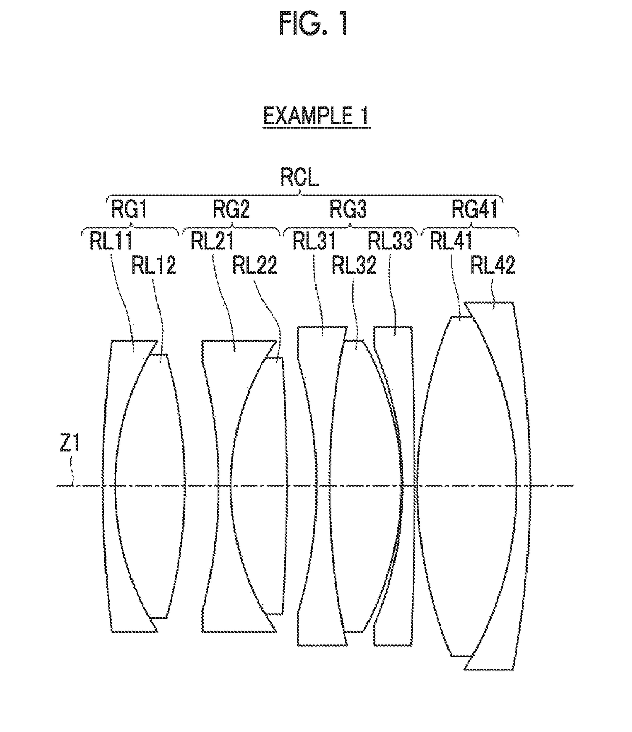
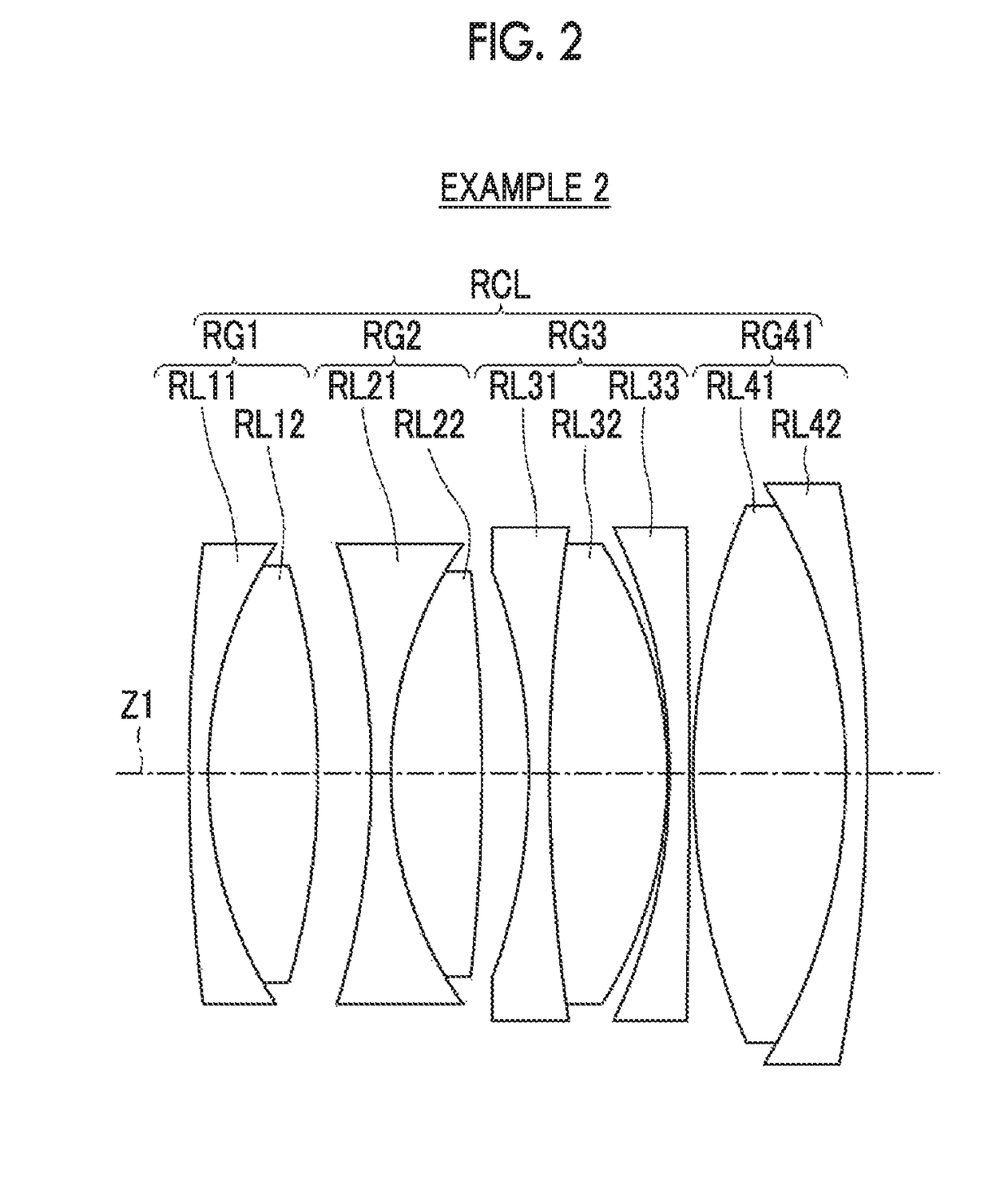
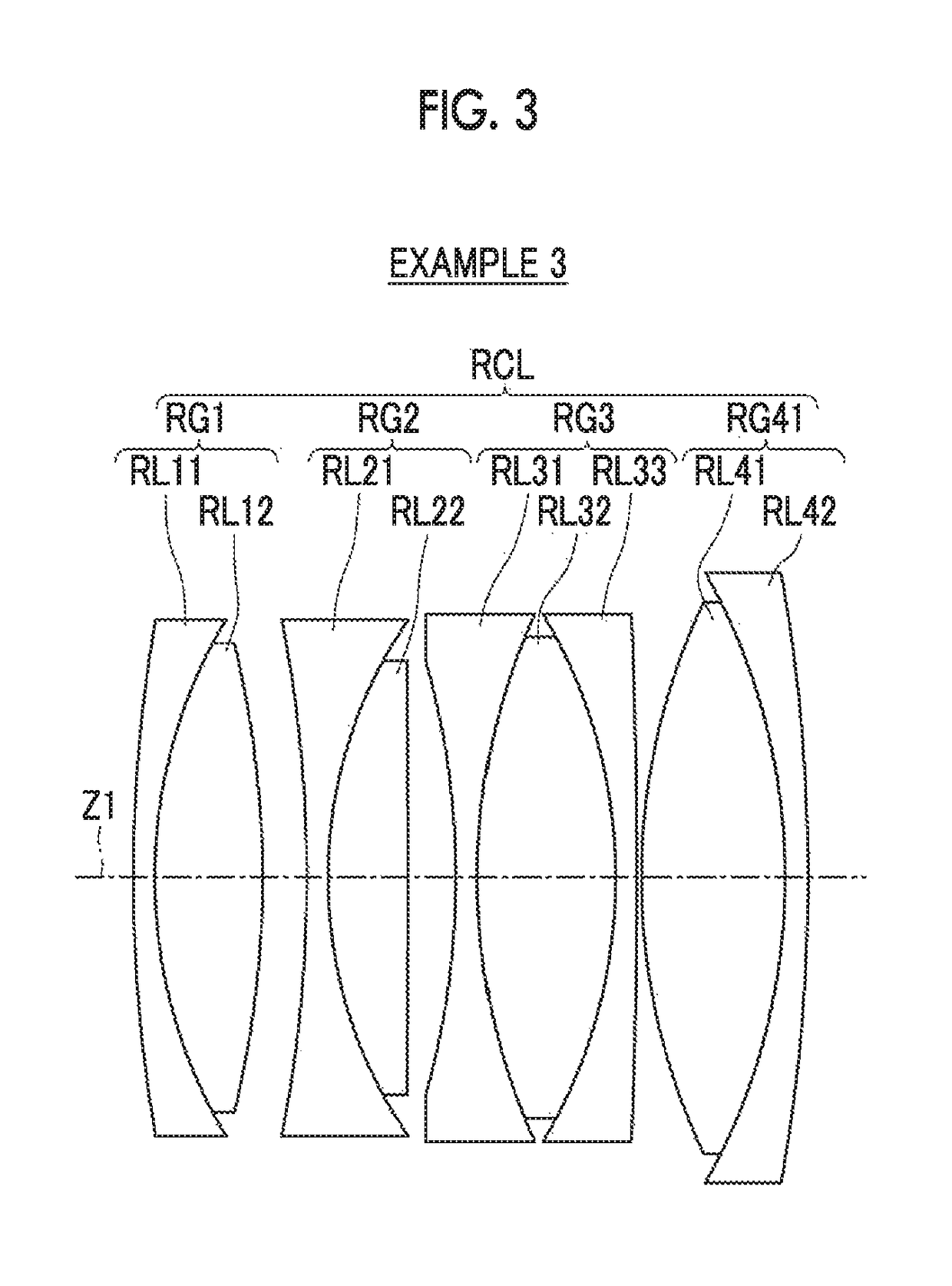
[0044]Hereinafter, an embodiment of the present invention will be described with reference to drawings. FIGS. 1 to 4 are cross-sectional views respectively illustrating first to fourth lens configuration examples of a rear converter lens RCL according to the embodiment of the present invention. In FIGS. 2 to 4, all basic configurations of the respective configuration examples are the same. Thus, hereinafter, description will be given on the basis of the configuration example shown in FIG. 1, and the configuration examples of FIGS. 2 to 4 will be also described as necessary. FIG. 5 is a lens cross-sectional view illustrating an overall configuration in a state where the rear converter lens RCL of FIG. 1 is mounted on a master lens ML. FIG. 6 is a ray diagram of an optical system shown in FIG. 5, and shows each optical path of on-axis rays 3 and rays 2 with the maximum angle of view in a state where an infinite object is in focus. In the rays 2 with the maximum angle of view, a princi...


PUM


Abstract

Provided are a rear converter lens and an imaging apparatus capable of achieving favorable optical performance and an appropriate back focal length with high magnification. The rear converter lens RCL consists of, in order from the object side, four lens-groups of positive, negative, negative, and positive lens-groups. In order from the object side, a first lens-group RG1 consists of a negative lens RL11 and a positive lens RL12, a second lens-group RG2 consists of a negative lens RL21 and a positive lens RL22, a third lens-group RG3 consists of a negative lens RL31, a positive lens RL32, and a negative lens RL33, and a fourth lens-group RG4 consists of a biconvex lens RL41 and a negative lens RL42. Here, 0.22<cf / f12<1 is satisfied, where f12 is a composite focal length of the first lens-group RG1 and the second lens-group RG2, and cf is a focal length of the rear converter lens RCL.

Description

CROSS-REFERENCE TO RELATED APPLICATIONS[0001]The present application claims priority under 35 U.S.C. § 119 to Japanese Patent Application No. 2016-061659, filed on Mar. 25, 2016. Each of the above application(s) is hereby expressly incorporated by reference, in its entirety, into the present application.BACKGROUND OF THE INVENTION[0002]1. Field of the Invention[0003]The present invention relates to a rear converter lens, which is detachably and attachably mounted on the image side of a master lens and in which a focal length of the whole system is increased, and an imaging apparatus comprising the rear converter lens.[0004]2. Description of the Related Art[0005]Conventionally, there are known rear converter lenses (rear conversion lenses) each of which is detachably and attachably mounted on a master lens (main lens) between a camera main body and the master lens and serves as an optical system in which a focal length of the whole lens system is increased. For example, JP2012-47869A...

Claims


Application Information

Patent Timeline
Patent Type & Authority Patents(United States)
IPC IPC(8): G03B17/56G02B9/52G02B9/54G02B15/10
CPCG03B17/565G02B15/10G02B9/54G02B9/52G02B15/12
Inventor ORI, TETSUYACHO, MICHIO
Owner FUJIFILM CORP
Why Eureka
Try Eureka