Battery assembly for a hearing device

a hearing device and battery technology, applied in the direction of batteries, coupling device connections, cell components, etc., can solve the problems of not being able to read or interpret drawings or diagrams, the user of the hearing device having bad finger dexterity, and the battery being required

Inactive Publication Date: 2019-02-05
OTICON
View PDF10 Cites 4 Cited by
  • Summary
  • Abstract
  • Description
  • Claims
  • Application Information

AI Technical Summary

Benefits of technology

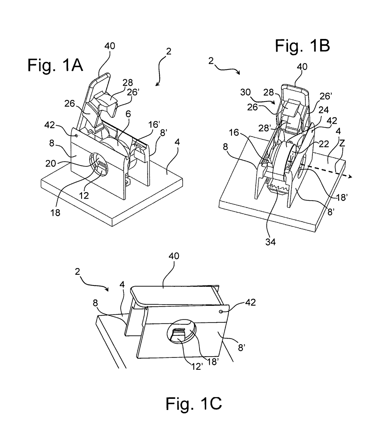
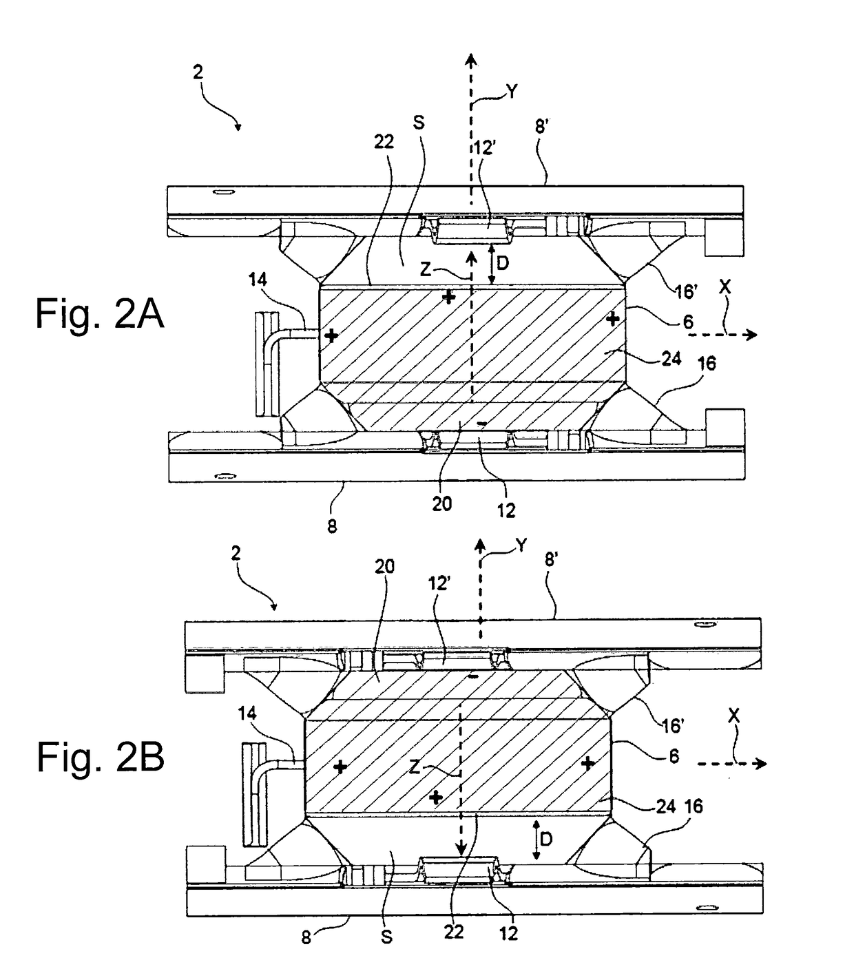
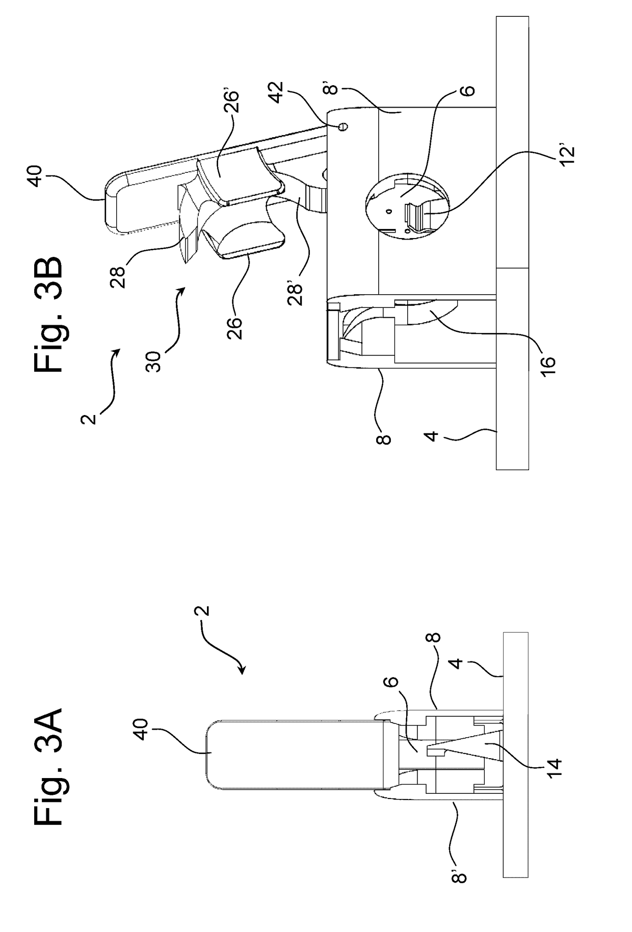
[0014]Hereby, the battery assembly makes it possible to install a battery into the battery assembly of a battery-operated hearing device without regard to the orientation of the battery. The battery assembly will automatically allow the battery polarities to be in contact with the correct compartment contacts so as to render the installed battery operative.
[0071]A protrusion member provided at the distal end of the second electrical connection member and / or the third electrical connection member makes it easier to establish an electrical contact between the pole (e.g. the negative pole) of the battery and the second electrical connection member or the third electrical connection member in dependence on the orientation of the battery in the battery assembly.

Problems solved by technology

Hearing device user having bad finger dexterity, are often challenged by inserting the battery correctly in the battery compartment of the hearing device such as a behind-the-ear (BTE) hearing aid.
This challenge is in particular a problem for hearing devices configured to be placed completely or almost completely in the ear canal (e.g. In-The-Ear (ITE) hearing devices).
The problem is typically, that the battery is required to be oriented in one predefined way in order to fit into the battery compartment.
Such drawings or diagrams may however, often be difficult to read or interpret by the hearing device user, especially in less than ideal lighting or when the hearing device user is a person of limited capacity to see, understand or implement the instructions implicit in the battery installation drawing or diagram.

Method used


Image

  • Battery assembly for a hearing device
  • Battery assembly for a hearing device
  • Battery assembly for a hearing device

Examples


Embodiment Construction

[0092]The detailed description set forth below in connection with the appended drawings is intended as a description of various configurations. The detailed description includes specific details for the purpose of providing a thorough understanding of various concepts. However, it will be apparent to those skilled in the art that these concepts may be practiced without these specific details. Several aspects of the apparatus are described by various blocks, functional units, modules, components, steps, processes etc. (collectively referred to as “elements”). Depending upon the particular application, design constraints or other reasons, these elements may be implemented using electronic hardware, computer programs, or any combination thereof.

[0093]The following disclosure is illustrated in relation to a hearing device such as a hearing aid. However, the skilled person would appreciate that the disclosed battery assembly may be used with other electronic devices as well.

[0094]The bat...


PUM

PropertyMeasurementUnit
electrical connectionaaaaaaaaaa
polaritiesaaaaaaaaaa
electricalaaaaaaaaaa

Abstract

A battery assembly for an electronic device such as a hearing aid is disclosed. The battery assembly includes; a compartment having a longitudinal axis and a transversal axis and being configured to receive and contain a battery; at least one electrical connection member for establishing electrical connection to a negative pole of the battery; at least one electrical connection member for establishing electrical connection to a positive pole of the battery; a guide structure configured to guide the battery into a predefined position in the compartment. The guide structure guides the battery into electrical connection with a first electrical connection member. A second electrical connection member when the battery is in a first configuration. The guide structure guides the battery into electrical connection with the first electrical connection member and a third electrical connection member when the battery has a reversed orientation.

Description

FIELD OF INVENTION[0001]The present disclosure relates to a battery assembly for a hearing device. More particularly, the present disclosure relates to a battery assembly that is able to properly accommodate an inserted battery regardless of orientation of the polarity of the inserted battery in the battery assembly.BACKGROUND[0002]Most hearing devices are energised by a small battery housed in a battery compartment. Hearing device user having bad finger dexterity, are often challenged by inserting the battery correctly in the battery compartment of the hearing device such as a behind-the-ear (BTE) hearing aid. This challenge is in particular a problem for hearing devices configured to be placed completely or almost completely in the ear canal (e.g. In-The-Ear (ITE) hearing devices).[0003]The problem is typically, that the battery is required to be oriented in one predefined way in order to fit into the battery compartment. A typical hearing device is operated by a battery that is i...

Claims


Application Information

Patent Timeline
Patent Type & Authority Patents(United States)
IPC IPC(8): H01M2/10H04R25/00H01M2/30
CPCH01M2/1038H04R25/602H01M2/30H01M2220/30H01R25/00H01M50/213Y02E60/10H01M50/216
Inventor PEDERSEN, TROELS HOLMSUNDBERG, OLIVER
Owner OTICON
Why Eureka
Try Eureka