
Permanent magnet maglev using passive, low-frequency electromagnetic stabilization

a permanent magnet and low-frequency electromagnetic stabilization technology, applied in the field of magnetic levitation (or “ maglev”) systems, can solve the problems of high instability, energy consumption of dissipation in the electromagnets of the train, and energy consumption of the dissipation of the eddy current in the guideway's induction coil, and achieve the effect of cost-effective construction and operation

Active Publication Date: 2019-02-19
VAN ROSENDALE JOHN
View PDF4 Cites 5 Cited by
  • Summary
  • Abstract
  • Description
  • Claims
  • Application Information

AI Technical Summary

Benefits of technology

The technical effect of this patent is to create a maglev system that is affordable to make and operate.

Problems solved by technology

The resulting equilibrium is, however, highly unstable so high-speed electronics on the train is used to adjust the current in the electromagnets hundreds of thousands of times per second to achieve stable levitation.
In EMS, dissipation in the electromagnets on the train consumes energy.
In EDS, dissipation of the eddy currents in the guideway's induction coils consumes energy.
In addition, there is substantial cost associated with powering electromagnets and / or building systems with superconducting magnets.
The challenge in this approach is Earnshaw's Theorem, which states that no static configuration of permanent magnets and ferromagnetic materials can provide stable levitation.
Thus the levitation created by the permanent magnets described in Post et al. is stable vertically but unstable horizontally.
Induction coils for such frequencies can be made using woven copper Litz wire and other technologies designed for high-frequencies, but the resulting system is more expensive and less efficient than systems operating at lower frequencies.

Method used


Image

  • Permanent magnet maglev using passive, low-frequency electromagnetic stabilization
  • Permanent magnet maglev using passive, low-frequency electromagnetic stabilization
  • Permanent magnet maglev using passive, low-frequency electromagnetic stabilization

Examples


Embodiment Construction

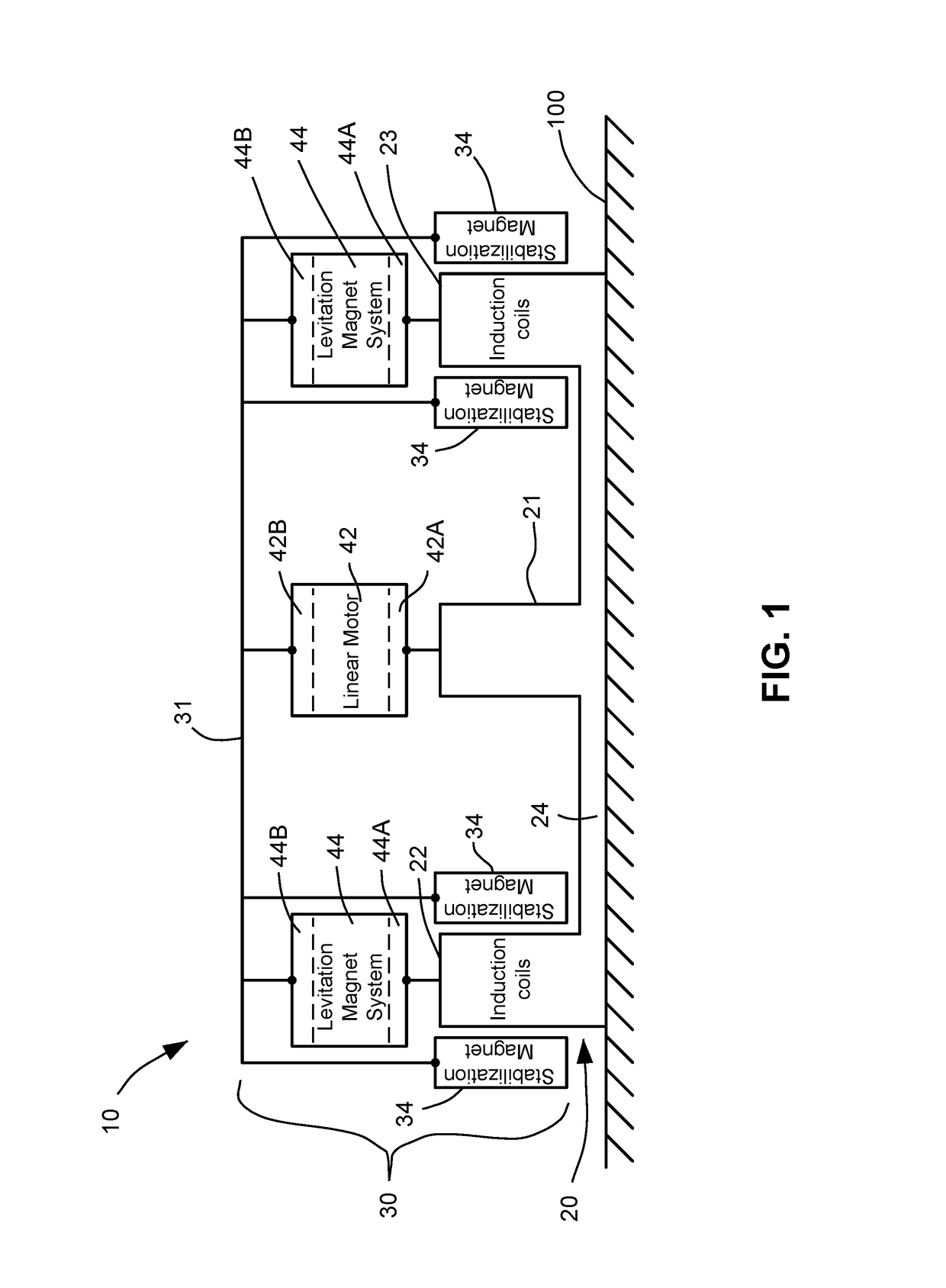
[0028]Referring now to the drawings and more particularly to FIG. 1, a maglev system that uses permanent magnet-based levitation in accordance with an embodiment of the present invention is illustrated. The system, generally referred to by numeral 10, includes two major elements referred to herein as a stationary guideway 20 and a vehicle 30 capable of movement relative to guideway 20. The components associated exclusively with guideway 20 will be indicated using reference numerals in the 20's and the components associated exclusively with vehicle 30 will be indicated using reference numerals in the 30's.

[0029]The system shown uses attraction of permanent magnets on vehicle 30 to ferromagnetic materials in guideway 20. As is known in the art, permanent magnet attraction can provide permanent levitation that is stable with respect to vertical disturbances but is unstable horizontally. This is a consequence of Earnshaw's Theorem which states that there can be no statically-stable levi...


PUM


Abstract

A magnetic levitation system includes a guideway and a vehicle. The guideway has ferromagnetic yokes and induction coils. The vehicle has levitation magnets for magnetic interaction with the ferromagnetic yokes wherein the vehicle levitates relative to the guideway. The vehicle has stabilization magnets coupled thereto for electromagnetic interaction with the induction coils as the vehicle travels along the guideway. Each stabilization magnet is a permanent magnet with a two-dimensional pattern of poles alternating in polarity in a first dimension and a second dimension.

Description

FIELD OF THE INVENTION[0001]The invention relates generally to magnetic levitation (or “maglev”) systems, and more particularly to a maglev system that uses simple permanent magnet-based levitation coupled with a novel system for stabilization in the horizontal dimension that is configurable to operate at efficient low frequencies.BACKGROUND OF THE INVENTION[0002]Magnetic levitation (or “maglev” as it is known) is a method of transport that moves vehicles in magnetic suspension along a guideway. Maglev can be faster, quieter, and more efficient than conventional railroad. Moreover, maglev eliminates the wear and vibration from the steel-on-steel contact of conventional railroads, greatly reducing right-of-way maintenance.[0003]There are currently two principal approaches to maglev, electromagnetic suspension (EMS) and electrodynamic suspension (EDS). In EMS, as exemplified by the German Transrapid Maglev, electromagnets on the train attract iron components in the guideway for levita...

Claims


Application Information

Patent Timeline
Patent Type & Authority Patents(United States)
IPC IPC(8): E01B25/30B60L13/04
CPCE01B25/30B60L13/04B60L2200/26
Inventor VAN ROSENDALE, JOHN
Owner VAN ROSENDALE JOHN
Learn More