
Papermachine fabric

a technology of papermachine fabric and fabric, which is applied in the field of papermachine fabric, can solve the problems of high cost and limit of batt structure production, and achieve the effect of producing more cost-effectively

Inactive Publication Date: 2006-12-14
VOITH PATENT GMBH
View PDF4 Cites 4 Cited by
  • Summary
  • Abstract
  • Description
  • Claims
  • Application Information

AI Technical Summary

Benefits of technology

[0009] The object of the present invention is to propose a papermachine fabric having a batt structure whose properties can be adapted simply to the respective customer-specific requirements and which, moreover, can be produced more cost-effectively than the papermachine fabrics with a batt structure known from the prior art.
[0011] As a result of providing at least one ultrathin batt section which extends over part of the width of the batt structure and has a thickness of 0.3 mm or less, it is possible to build up the batt structure from one or more of the ultrathin and cost-effectively prefabricated batt sections in accordance with the specific requirements on the fabric, irrespective of its overall thickness and overall width.
[0018] A plurality of such ultrathin fiber batts can then be joined flatly to one another in order to form at least one part of the batt structure. In this way, the batt structure can be built up simply and cost-effectively from the prefabricated ultrathin batt sections virtually in any desired thickness graduation and with virtually any desired properties in accordance with the customer requirements.
[0025] In this case, it is both possible for the ultrathin batt sections of an ultrathin fiber batt to have the same thickness or for at least one of the ultrathin batt sections of the ultrathin fiber batt to have a different thickness than the remaining ultrathin batt sections of the ultrathin fiber batt. In the last-named case, it is also conceivable for a plurality of ultrathin batt sections to be arranged above one another and jointly to have a height which corresponds to the height of the adjacent ultrathin batt sections of the same ultrathin fiber batt adjacent to the former. In this way, it is possible to form an ultrathin fiber batt having a uniform height.

Problems solved by technology

As a result of using the relatively thick fiber batts, limits are placed on the variability in the production of the batt structures.
In the case of the known fiber batts, this often requires individual production of the fiber batts specifically for the respective customer requirements, which often makes the costs for the production of such fabrics expensive.

Method used


Image

  • Papermachine fabric
  • Papermachine fabric
  • Papermachine fabric

Examples


first embodiment

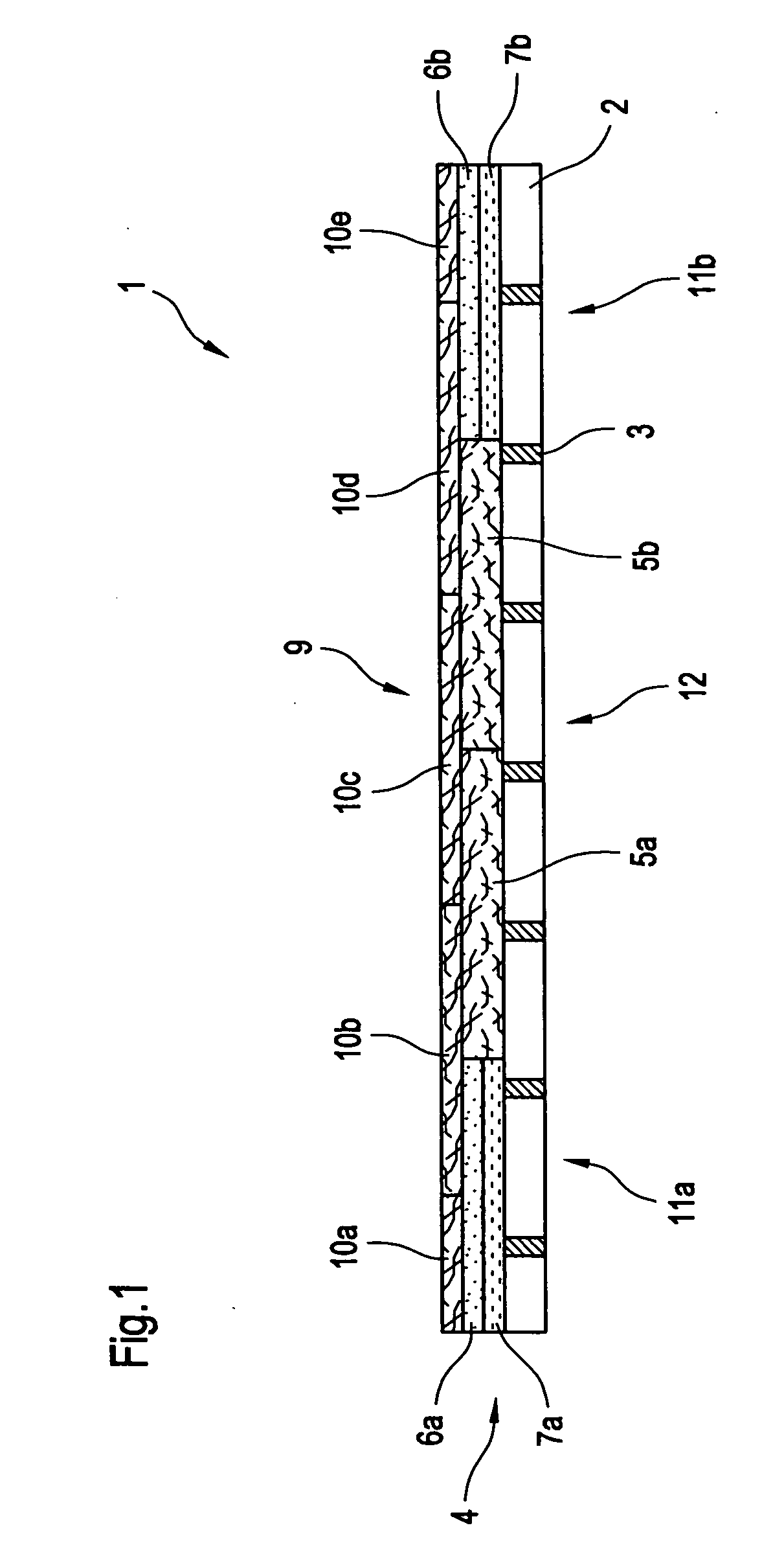
[0043]FIG. 1 shows in cross-section over its entire width a papermachine fabric according to the invention, formed as a dryer fabric 1.

[0044] The dryer fabric 1 has a carrier structure 2 which is formed by a perforated film 2 having openings 3. In the FIG. 1, above the perforated film, there is arranged a first ultrathin fiber batt 4, which is formed by ultrathin batt sections 5a, 5b, 6a, 6b and 7a, 7b.

[0045] The batt sections 6a and 7a and the batt sections 6b and 7b are in each case arranged flatly on one another and form a first laminate 8a and a second laminate 8b. The two laminates 8a and 8b are in each case arranged in the edge region 11a and 11b of the dryer fabric 1, the ultrathin batt sections 5a and 5b being arranged in the central region of the dryer fabric 1.

[0046] In order to form the ultrathin fiber batt 4 extending over the entire width of the fabric 1, the fiber batts 5a and 5b and the first and the second laminate 8a, 8b are arranged adjoining one another in their...

second embodiment

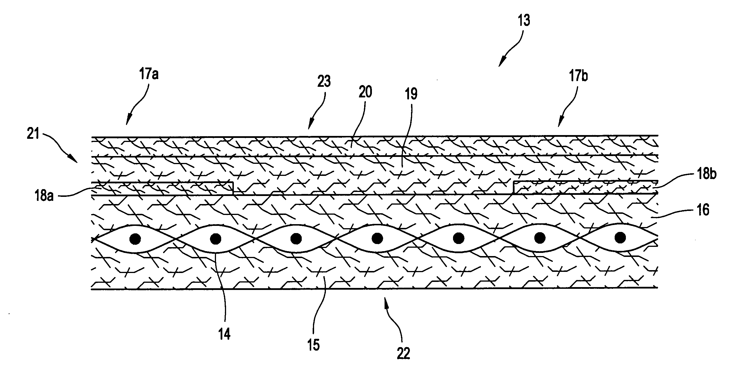
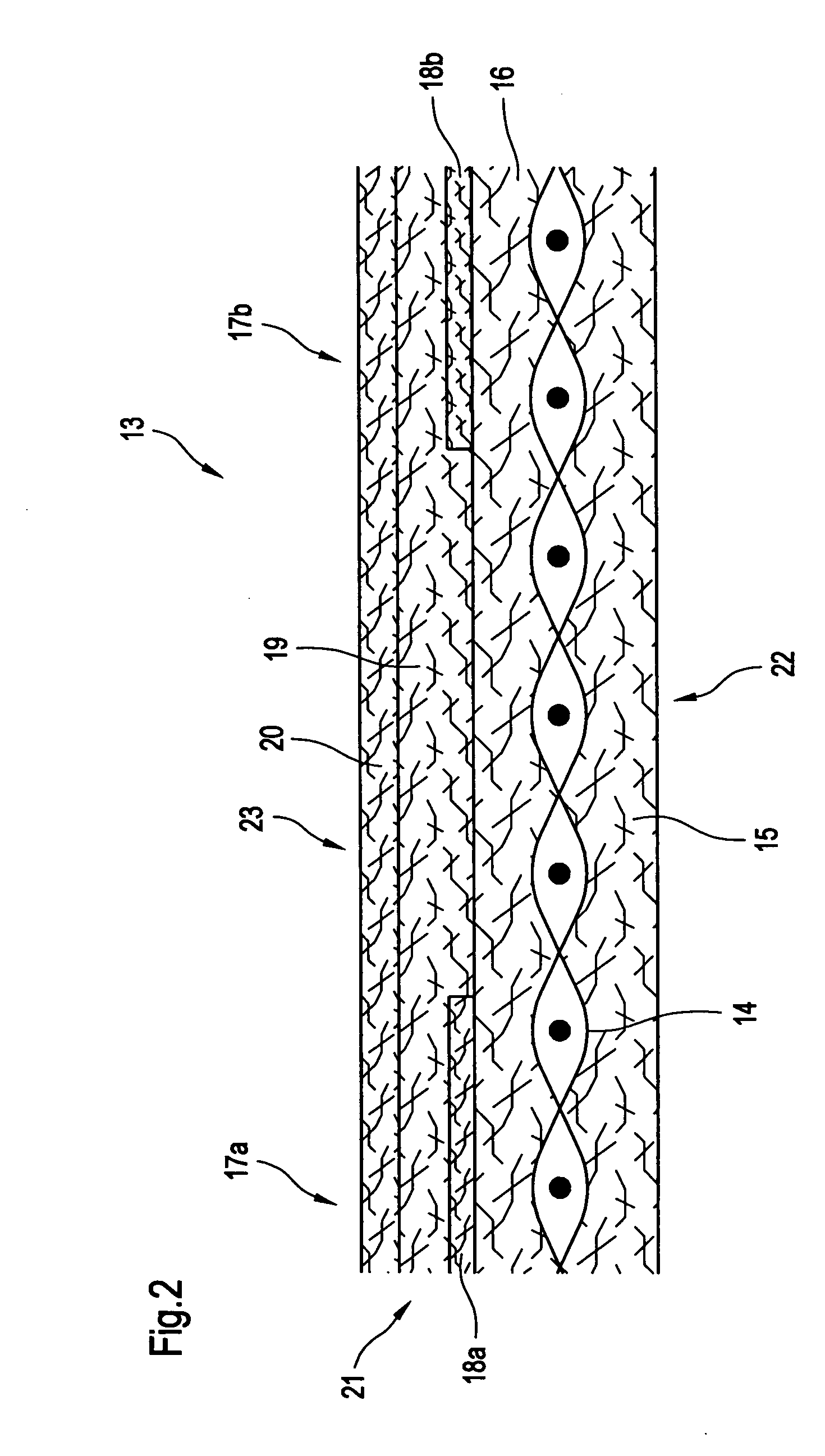
[0052]FIG. 2 shows in a cross section over its entire width a paper machine fabric according to the invention, formed as a press felt 13.

[0053] The press felt 13 has a carrier structure 14 which is formed by a woven fabric 14 known in the papermachine fabric sector. Furthermore, the press felt 13 has a batt structure 21.

[0054] The batt structure 21 has conventional fiber batts 15 and 16 which, in FIG. 2, are arranged above and below the woven fabric 14 and are joined flatly to the latter.

[0055] Furthermore, the batt structure 21 has conventional fiber batts 19 and 20 and ultrathin batt sections 18a and 18b according to the invention. The ultrathin batt sections 18a, 18b are in each case arranged in one of the edge regions 17a and 17b of the press felt 13, between the fiber batts 16 and 19.

[0056] The two ultrathin batt sections 18a, 18b each have a thickness of 0.1 mm, whereas the conventional fiber batts 16 and 19 have thicknesses in the range from 1.2 mm to 1.8 mm with thickness...

third embodiment

[0058]FIG. 3 shows in a cross section over its entire width a paper machine fabric according to the invention, formed as a press felt 24.

[0059] The press felt 24 has a carrier structure 25 which is formed by a laid scrim having filaments 27 extending in the machine direction. In FIG. 3, above the carrier structure 25, there is arranged a batt structure 26 which is joined flatly to the carrier structure 25.

[0060] The batt structure 26 has ultrathin fiber batts 28, 29, 30, 31 and 32 which are ranged above one another flatly from bottom to top in FIG. 3.

[0061] In the two edge regions 33a and 33b of the press felt 24, ultrathin batt sections 35a and 35b are, moreover, arranged between the two ultra thin fiber batts 30 and 31. Furthermore, two ultrathin batt sections 36a and 36b adjoining one another in their width extent are arranged in the central region 34 between the two fiber batts 31 and 32.

[0062] Each of the ultrathin fiber batts 28, 29, 30, 31 and 32 is formed by a plurality o...


PUM


Abstract

The invention relates to a papermachine fabric having a batt structure extending over the entire width of the fabric, the batt structure comprising at least one ultrathin elongated fiber batt which extends over a part width of the fabric and has a thickness of 0.3 mm or less.

Description

CROSS-REFERENCE TO RELATED APPLICATIONS [0001] The present application claims priority under 35 U.S.C. § 119 of German Patent Application No. 10 2005 023 390.2 filed on 20 May 2005, the disclosures of which is expressly incorporated by reference herein in its entirety. BACKGROUND OF THE INVENTION [0002] 1. Field of the Invention [0003] The invention relates to a papermachine fabric for use in a paper, board or tissue machine. [0004] 2. Description of Background [0005] In order to reduce the production costs for papermachine fabrics, the aim of current developments is often to provide modularly constructed papermachine fabrics. [0006] One possibility for the modular construction of papermachine fabrics consists in providing carrier or reinforcing structures which are built up from basic elements that are prefabricated and joined to one another, such as threads and / or flat structures such as films or the like. [0007] In the production of papermachine fabrics, use is currently made of ...

Claims


Application Information

Patent Timeline
IPC IPC(8): D21F1/00D21F7/08D04H1/08
CPCD21F7/083D21F1/0036Y10T442/50Y10T442/608
Inventor WESTERKAMP, ARVED
Owner VOITH PATENT GMBH
Learn More