Cooling-assisted, heat-generating electrical component and method of manufacturing same

Inactive Publication Date: 2005-12-29
EASTMAN KODAK CO
View PDF8 Cites 2 Cited by
  • Summary
  • Abstract
  • Description
  • Claims
  • Application Information

AI Technical Summary

Benefits of technology

[0011] The present invention has numerous advantages over existing developments including reliability, cost effectiveness, ease of development, and increased component useful life. Moreover, the present in

Problems solved by technology

It is well known that overheating of electrical components, for instance components mounted on a circuit board, contributes to reducing the life of the component.
Overall component reliability is also compromised by excessive overheating during service.
As circuit boards become denser and contain components that have higher power output capacity, reliability problems become magnified for solder joints of the circuit board, particularly in “chip” ceramic type parts due to CTE (Coefficient of Therma

Method used


Image

  • Cooling-assisted, heat-generating electrical component and method of manufacturing same
  • Cooling-assisted, heat-generating electrical component and method of manufacturing same
  • Cooling-assisted, heat-generating electrical component and method of manufacturing same

Examples


Example

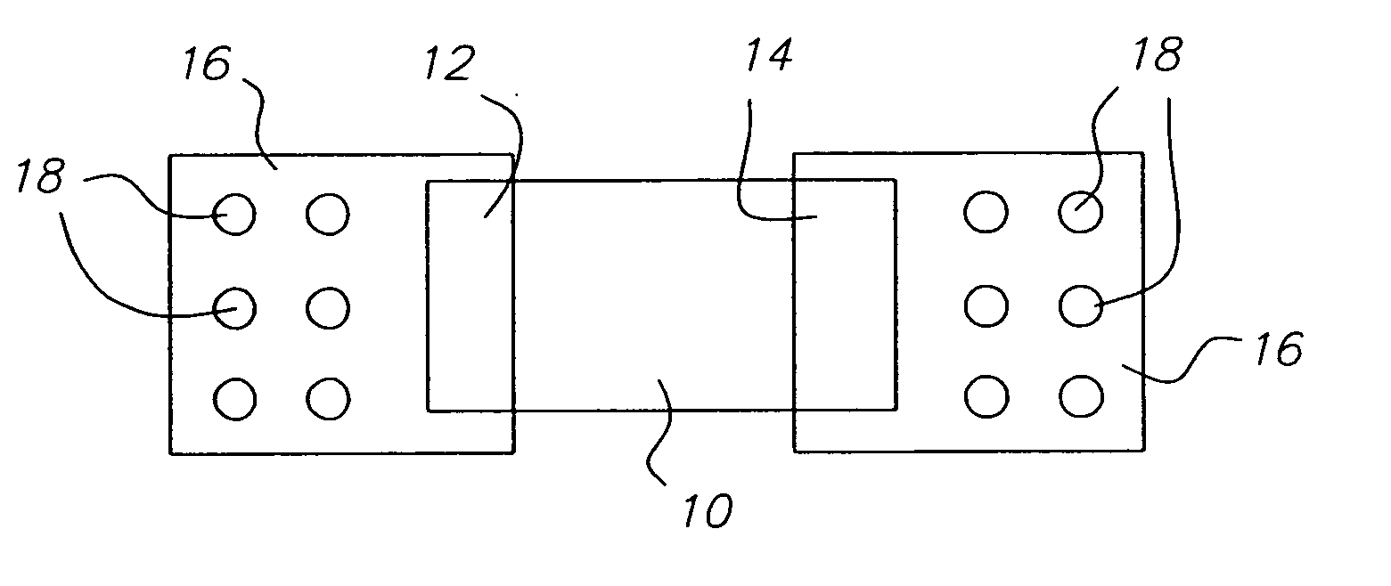
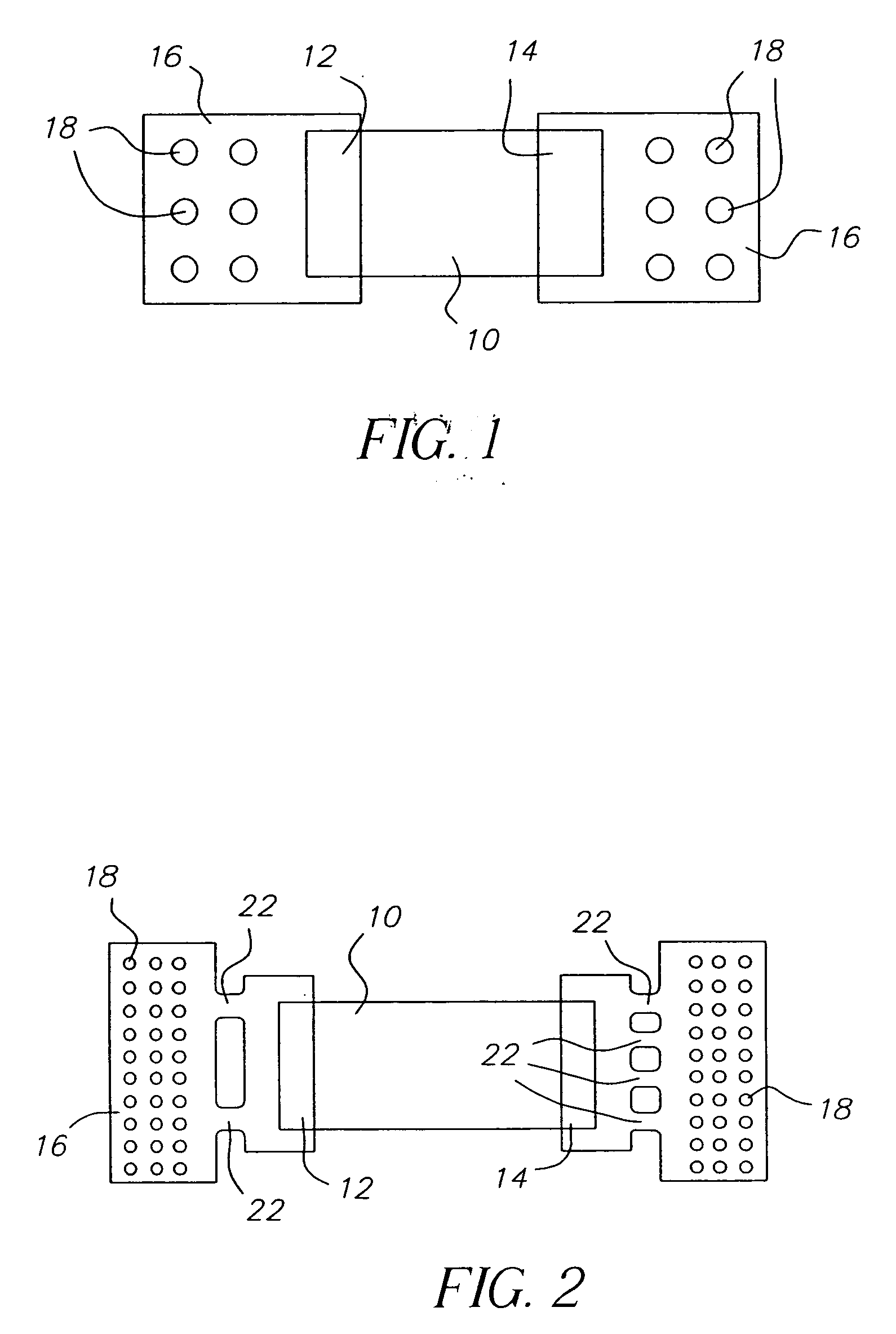
[0017] Turning now to the drawings, and in particular to FIGS. 1 and 2, the electrical component 10 of the invention is illustrated. According to FIG. 1, electrical component 10, for instance a resistor or capacitor, has mating portions 12, 14 and a heat-removing element 16 attached to either of mating portions 12, 14. Electrical component 10 is preferably made of a ceramic or ceramic-like material for suitability of die usage or affixing other electrical components (multi-chip module). Although soldering is the preferred method of attaching heat-removing element 16 to either of mating portions 12, 14, skilled artisans will appreciate that other methods may be used including using electrically conductive adhesives. Mating portions 12, 14 are typically gold or palladium tipped for best thermal conductivity and solderability. Skilled artisans will appreciate that, alternatively, the mating portions 12, 14 may comprise other thermally conductive materials such as tin-lead.

[0018] Accor...


PUM


Abstract

A cooling-assisted, heat-generating electrical component reduces heat generated during operation. The electrical component, typically a resistor, has a least one heat-removing element electrically associated therewith. Heat-removing element comprises a plurality of thermal vias therein and is fixedly attached to an end portion of the electrical component, typically on opposed end portions. Heat absorbed by the heat-removing element can be transported away from the electrical component during service.

Description

CROSS-REFERENCE TO RELATED APPLICATIONS [0001] The present application is related to U.S. application Ser. No. ______(Docket 84843), filed ______, by Tina P. Barcley, and entitled, “Insitu-Cooled Electrical Assemblage And Method Of Manufacturing Same;” and U.S. application Ser. No. ______(Docket 84844), filed ______, by Tina P. Barcley, and entitled, “Method of Cooling Heat-Generating Electrical Components.”FIELD OF THE INVENTION [0002] The invention relates to improvements in heat transfer in electronic technology. More particularly, the invention concerns electrical assemblages, such as circuit boards, which reduce heat generated in ceramic “chip” components during service. BACKGROUND OF THE INVENTION [0003] It is well known that overheating of electrical components, for instance components mounted on a circuit board, contributes to reducing the life of the component. Overall component reliability is also compromised by excessive overheating during service. As circuit boards becom...

Claims


Application Information

Patent Timeline
IPC IPC(8): F28F7/00H05K1/02H05K1/11H05K3/34
CPCH05K1/0206H05K1/113H05K1/114H05K2201/10636H05K2201/062H05K2201/0969H05K2201/09781H05K3/3442Y02P70/50
Inventor BARCLEY, TINA P.
Owner EASTMAN KODAK CO
Why Eureka
Try Eureka