Cable winch device

Active Publication Date: 2015-04-28
LIEBHERR WERK NENZING
View PDF13 Cites 0 Cited by
  • Summary
  • Abstract
  • Description
  • Claims
  • Application Information

AI Technical Summary

Benefits of technology

[0005]Therefore, it is the object of the present invention to develop a cable winch device as well as a crane as mentioned above in an advantageous way, in p

Problems solved by technology

In the hoisting gear operation at certain hook heights it may occur that the cable constantly operates in the alternation of two positions and due to the increased surface pressure in this region thus is subject to an increased wear.
This increased wear re

Method used


Image

  • Cable winch device
  • Cable winch device

Examples


Example

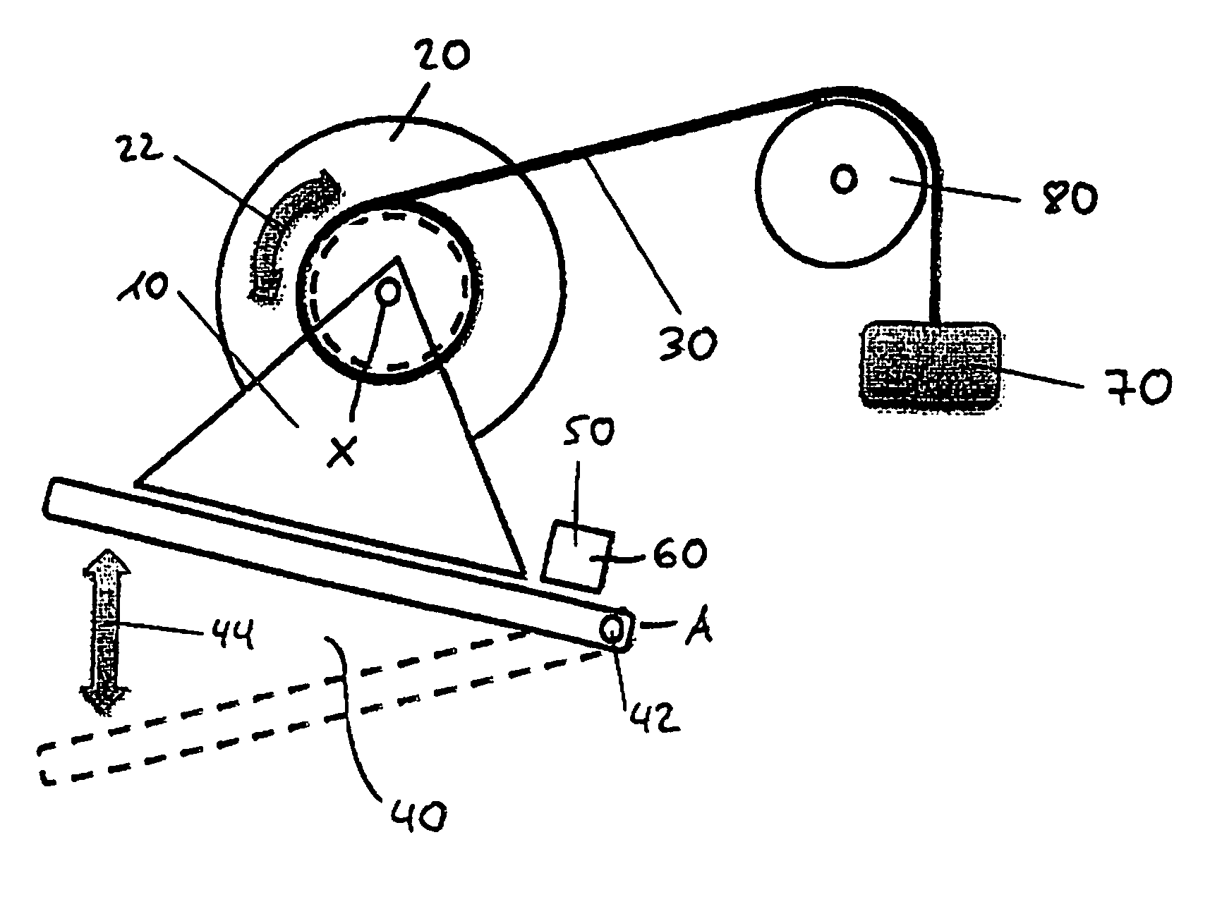
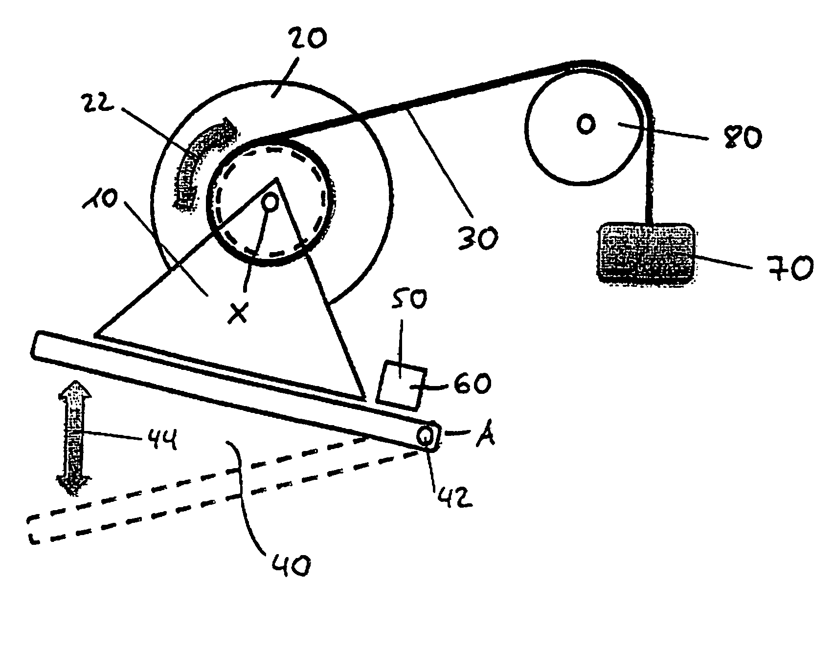
[0022]FIG. 1 shows a schematic representation of a cable winch device 10 according to the invention in an advantageous embodiment with a cable winch 20 on which a cable 30 is partly wound up.

[0023]There is provided a tilting means 40 by means of which the cable winch 20 can at least partly be tilted and / or pivoted about an axis A, which is substantially parallel to the longitudinal axis X of the cable winch 20. The tilting means 40 includes one or more, preferably two tilt joints 42 and one or more drive means 44. The drive means 44 for example is a linear drive or a rotary drive and according to the embodiment shown in FIG. 1 a hydraulically actuated hoisting cylinder 44. In principle, however, the drive means can be a hydraulic, pneumatic or electric or some other suitable drive means.

[0024]The cable winch 20 includes at least one cable winch drive means 22 by means of which the cable winch is rotatable such that the cable 30, which for example is guided over the cable pulley 80, ...


PUM


Abstract

A cable winch device, in particular a cable winch device of a crane with at least one cable winch, with at least one cable, wherein the cable is at least partly wound up on the cable winch and/or can be wound up and/or unwound, and with at least one tilting means by means of which the cable which can at least partly be tilted and/or pivoted about an axis which is substantially parallel to the longitudinal axis of the cable winch. A crane is also disclosed herein.

Description

BACKGROUND OF THE INVENTION[0001]The present invention relates to a cable winch device, in particular a cable winch device of a crane with at least one cable winch, with at least one cable, wherein the cable is at least partly wound up on the cable winch and / or can be wound up and / or unwound, and to a crane with at least one cable winch device.[0002]Cranes, such as deep-sea cranes, but in principle also any cranes which have a main working range in the transition from one position to another position, include at least one cable winch device or a reeling device, which operates in particular in the hoisting gear operation.[0003]In the hoisting gear operation at certain hook heights it may occur that the cable constantly operates in the alternation of two positions and due to the increased surface pressure in this region thus is subject to an increased wear. This increased wear reduces the useful life of the cable and thus leads to a premature failure of the cable.[0004]In principle, h...

Claims


Application Information

Patent Timeline
IPC IPC(8): B66D1/00B66D1/28B66D1/36
CPCB66D1/28B66D1/365
Inventor KRAPPINGER, REINHARDSCHOBESBERGER, EUGENKOHLER, ALEXANDER
Owner LIEBHERR WERK NENZING
Why Eureka
Try Eureka