Keyboard device and key structure thereof

Active Publication Date: 2021-06-17
PRIMAX ELECTRONICS LTD
View PDF0 Cites 1 Cited by
  • Summary
  • Abstract
  • Description
  • Claims
  • Application Information

AI Technical Summary

Benefits of technology

[0008]Another object of the present invention provides a keyboard device wit

Problems solved by technology

The dust accumulation may cause the interference and the unsmooth operation of the key structure 11 and affect the operating feel of the user.
Mo

Method used


Image

  • Keyboard device and key structure thereof
  • Keyboard device and key structure thereof
  • Keyboard device and key structure thereof

Examples


Embodiment Construction

[0022]The embodiments of present invention will be described more specifically with reference to the following drawings. Generally, in the drawings and specifications, identical or similar components are designated by identical numeral references. For well understanding the present invention, the elements shown in the drawings are not in scale with the elements of the practical product. In the following embodiments and drawings, the elements irrelevant to the concepts of the present invention or the elements well known to those skilled in the art are omitted. It is noted that numerous modifications and alterations may be made while retaining the teachings of the invention.

[0023]Please refer to FIGS. 5, 6 and 7. FIG. 5 is a schematic perspective view illustrating the outer appearance of a keyboard device according to an embodiment of the present invention. FIG. 6 is a schematic perspective view illustrating a portion of the keyboard device as shown in FIG. 5. FIG. 7 is a schematic ex...


PUM


Abstract

A keyboard device includes a membrane circuit board and a key structure over the membrane circuit board. The key structure includes a keycap, a plunger structure, a key pedestal and an elastic element. The plunger structure is arranged between the keycap and the elastic element. At least a portion of the keycap is disposed within a pedestal dust-storage chamber of the key pedestal. At least a portion of the plunger structure is disposed within a guiding chamber of the key pedestal. Due to the relative location between the keycap, the plunger structure and the key pedestal, the path of the dust to enter the guiding chamber is extended or blocked. Consequently, the dust-proof efficacy is enhanced.

Description

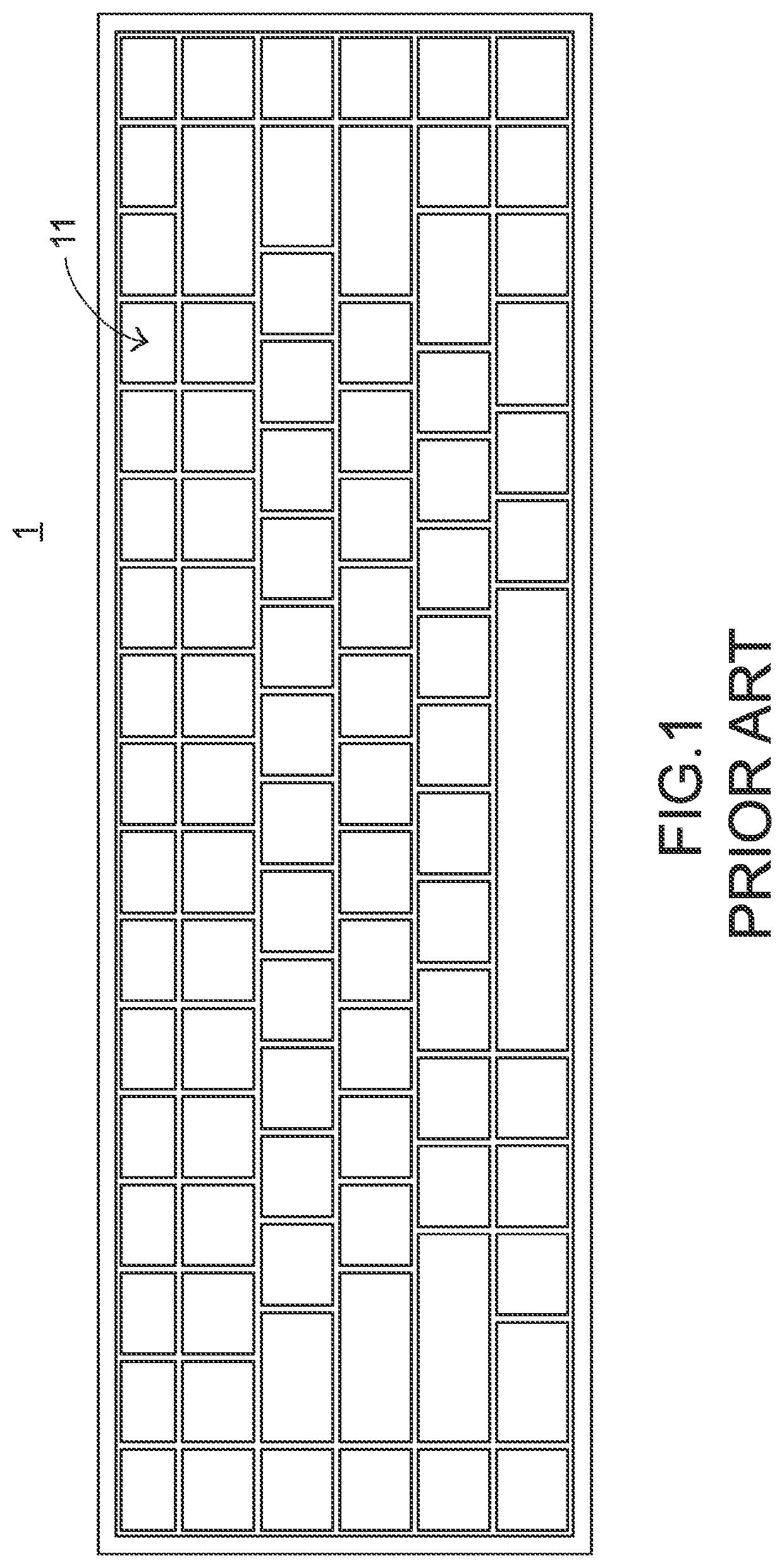
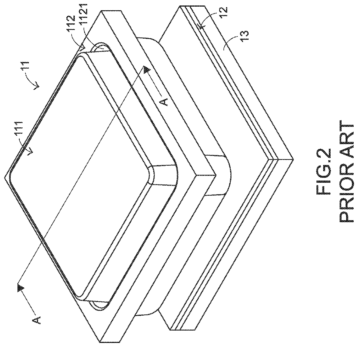
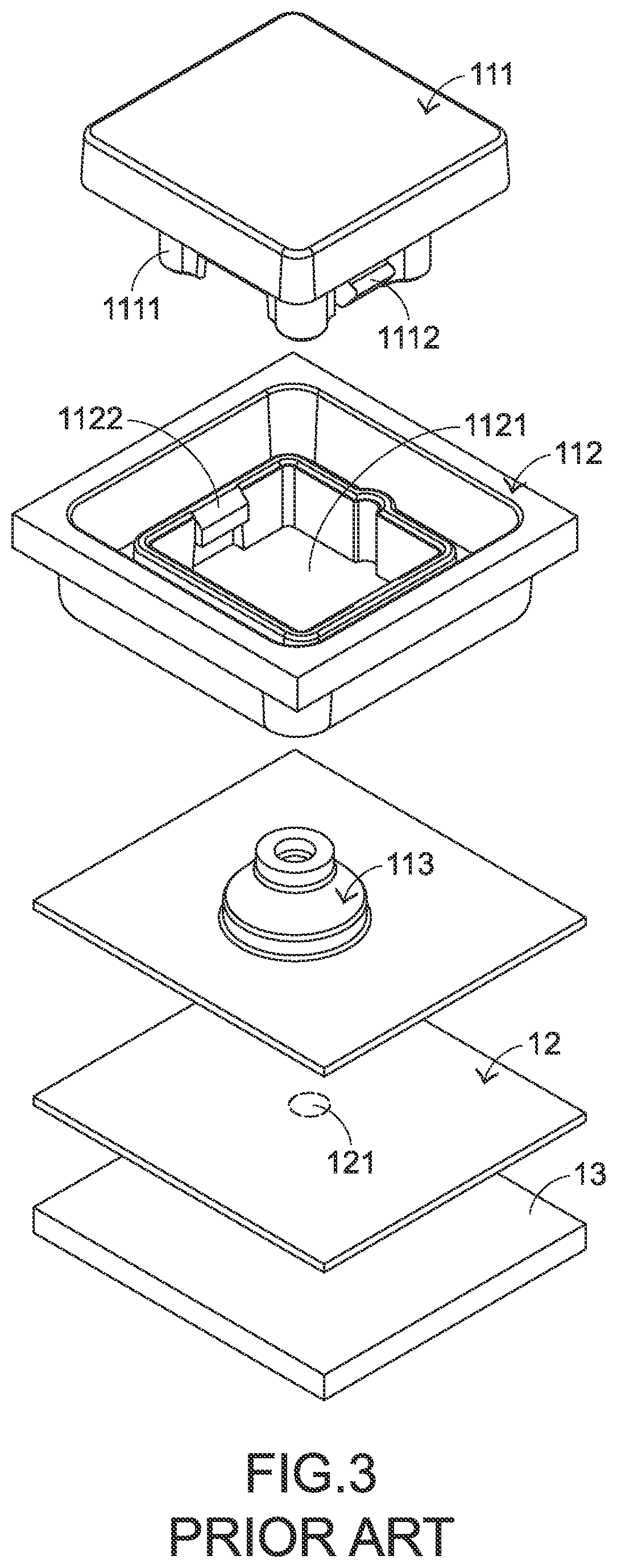
FIELD OF THE INVENTION[0001]The present invention relates to a computer peripheral device, and more particularly to an input device.BACKGROUND OF THE INVENTION[0002]Generally, the widely-used peripheral input device of a computer system includes for example a mouse device, a keyboard device, a trackball device, or the like. Via the keyboard device, characters or symbols can be inputted into the computer system directly. As a consequence, most users and most manufacturers of input devices pay much attention to the development of keyboard devices.[0003]The structures and the functions of a conventional keyboard device will be illustrated as follows. Please refer to FIGS. 1, 2, 3 and 4. FIG. 1 is a schematic perspective view illustrating the outer appearance of a conventional keyboard device. FIG. 2 is a schematic perspective view illustrating a portion of the keyboard device as shown in FIG. 1. FIG. 3 is a schematic exploded view illustrating a portion of the keyboard device as shown ...

Claims


Application Information

Patent Timeline
IPC IPC(8): G06F3/02H01H13/705
CPCG06F3/0202H01H13/705H01H13/88H01H2235/008H01H2233/03H01H2221/026H01H2223/002H01H13/14H01H13/52H01H13/7065H01H2233/07H01H2213/014H01H3/12
Inventor CAI, LIU-BINGCHEN, LI-QIANG
Owner PRIMAX ELECTRONICS LTD
Why Eureka
Try Eureka