
Operating device and motor vehicle seat

a technology of operating device and motor vehicle seat, which is applied in the direction of vehicle seats, movable seats, vehicle arrangements, etc., can solve the problems of operator errors, touch-sensitive surfaces outside the operator's field of view are not recommended, and operator errors may have unforeseen consequences, so as to facilitate the operator's orientation

Inactive Publication Date: 2019-02-26
FAURECIA AUTOSITZE
View PDF28 Cites 0 Cited by
  • Summary
  • Abstract
  • Description
  • Claims
  • Application Information

AI Technical Summary

Benefits of technology

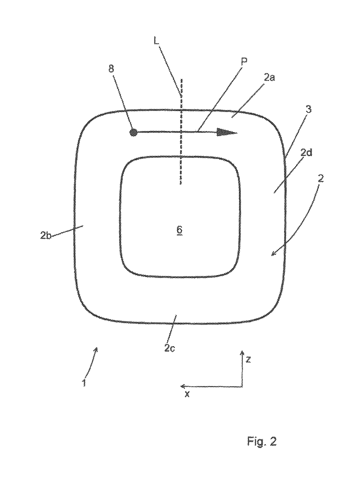
[0011]The control device according to the invention has at least one recess, within which the touch-sensitive surface is located. In this manner, it is possible for an operator to feel the touch-sensitive surface which is designed to generate a control signal to control a device—e.g. a car seat function—when touched even when it is outside their field of view and to be guided by in the adjustment of the desired function. This is done through the recess, which can be designed as a groove or slot and which preferably has a particularly ergonomic U-shaped, V-shaped or L-shaped cross section, which accommodates the operator's finger. In this manner, the control device according to the invention is easy for the operator to feel on the one hand and reliably prevents the operator's finger from slipping and therefore prevents unintentional adjustments from being made on the other. Provision may likewise be made for one of the edges, the inner or outer edge of the recess (in relation to the bottom or deepest point of the recess) being higher than the other edge defining the recess. This can allow for spatial orientation on the control device according to the invention since the operator can feel, at all points on the control device, where they are and thus which adjustment options can be touched. In this case, the finger does not therefore need to touch any other points or surfaces in order for the operator to orient themselves.
[0013]The course of the recess can be in a multitude of different geometrical forms, such as an L-shape or a U-shape or an I-shape or other shapes. The control device according to the invention can also have a plurality of discontinuous recesses which can all be allocated to different functions. A design in which the recess runs around a central section of the control device is preferred. If it surrounds the central section fully then the recess and thus the touch-sensitive surface positioned within it form a closed area. Above all, this offers better operational reliability since the finger is prevented from slipping or from leaving the recess on one side.
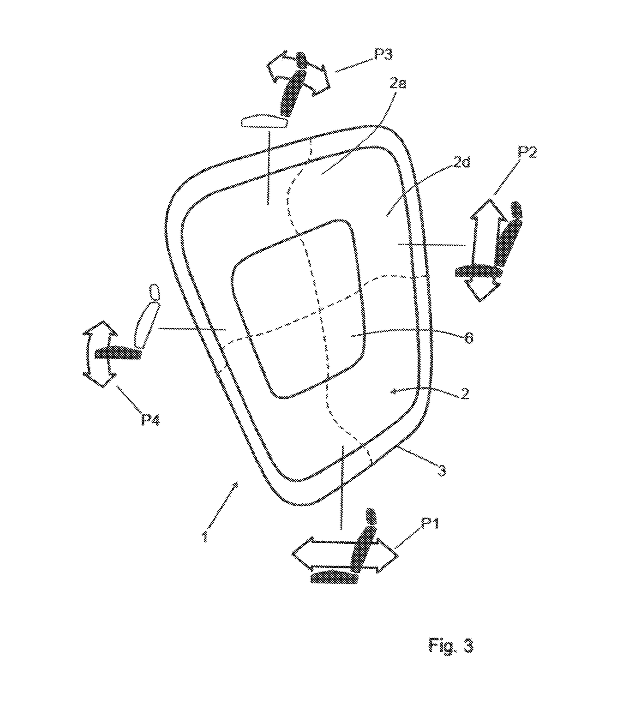
[0015]A preferred embodiment has a substantially L-shaped flow of the recess along its length. This can then be designed, for example, so that there is an area which is raised in comparison with the recess which likewise has at least one touch-sensitive surface. The raised area can also have a substantially L-shaped design along its length. Furthermore, the two L-shapes can be arranged so that the substantially L-shaped raised area and the substantially L-shaped recess complete each other to form a substantially rectangular shape. In this manner, a simple geometric shape is created in which it is easy for the operator to orient themselves since they can recognize by touch alone where they are on the control device.

Problems solved by technology

The problem with touch-sensitive surfaces is that they are relatively hard to find outside the operator's field of view and this can lead to operator errors.
For this reason, such touch-sensitive surfaces outside the operator's field of view are not recommended, particularly if operation is to be possible while driving the vehicle.
Possible operator errors may have unforeseen consequences.

Method used


Image

  • Operating device and motor vehicle seat
  • Operating device and motor vehicle seat
  • Operating device and motor vehicle seat

Examples


Embodiment Construction

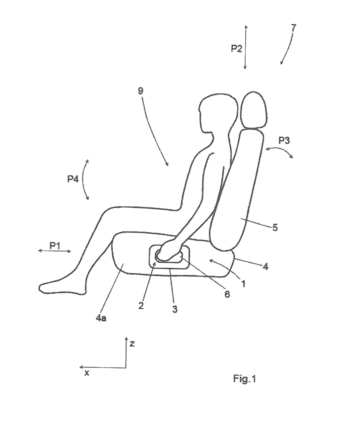
[0027]The motor vehicle seat 7 shown in FIG. 1 has a seat section 4 and a back rest 5 attached to it in the usual manner. A variety of seat adjustments can be provided for on the seat 7: in particular, a forward-backward seat adjustment indicated by the arrow P1 which can be used to move the seat in the direction of travel X or against the direction of travel X. In addition, there can be a seat height adjustment seat adjustment option which is indicated by the arrow P2 and with which the seat 7 can be raised up or lowered down as a whole in a vertical direction Z. A back rest angle adjustment can also be provided with which the back rest 5 can be tilted in relation to the seat section 4, indicated by the arrow P3. Finally, it is also possible for the seat 7 as a whole to be tilted forwards or backwards using a seat pivot adjustment device as indicated by the arrow P4. All of these and other functions, in particular seat functions such as seat heating or similar, can be operated via ...


PUM


Abstract

A control device (1), in particular for car seats (7), with at least one touch-sensitive surface (2). This is designed to generate a control signal for controlling a function, in particular a car seat function, when touched by the hand of an operator. The control device (1) has at least one recess (3) within which the touch-sensitive surface (2) is positioned.

Description

STATEMENT OF RELATED APPLICATIONS[0001]The application is the US National Phase of International Application No. PCT / EP2015 / 000313 having an International Filing Date of 13 Feb. 2015, which claims priority on German Patent Application No. 10 2014 002 919.0 having a filing date of 28 Feb. 2014.BACKGROUND OF THE INVENTION[0002]Technical Field[0003]The invention concerns a control device, in particular for car seats, with at least one touch-sensitive surface designed to generate a control signal for controlling a function, in particular a car seat function, when touched by the hand of an operator, wherein the control device has at least one recess within which the touch-sensitive surface (2) is positioned, characterized in that the recess is designed as a groove or slot to accommodate the operator's fingers, and a motor vehicle seat equipped with such a control device, having a seat section and a back rest as well as the control device.[0004]Prior Art[0005]For some time, it has been co...

Claims


Application Information

Patent Timeline
Patent Type & Authority Patents(United States)
IPC IPC(8): B60N2/02B60N2/16B60N2/22B60N2/06
CPCB60N2/0228B60N2/22B60N2/16B60N2/06
Inventor GERDING, RAINERROHRKASTE, BERND
Owner FAURECIA AUTOSITZE
Learn More