Mixing device for joint compound

a technology of mixing device and compound, which is applied in the direction of mixing, chemistry apparatus and processes, mixers, etc., to achieve the effect of enhancing mixing and enhancing the durability of the blad

Active Publication Date: 2019-03-05
BUDDY TOOLS
View PDF4 Cites 1 Cited by
  • Summary
  • Abstract
  • Description
  • Claims
  • Application Information

AI Technical Summary

Benefits of technology

[0006]A mixing device in accordance with the present invention includes a blade with radially outwardly extending arms and / or with a longitudinally extending wall with an elliptical cross-section. The elliptical cross-section may synergistically provide enhanced mixing and enhanced durability of the blade compared to previously known joint compound mixers. For example, the elliptical cross section may provide structural support to the radially outwardly extending arms and / or the longitudinally extending walls while allowing the radially outwardly extending arms and / or the longitudinally extending walls to cut through and spread joint compound.
[0007]The structural support may allow the blade to be made of a plastic material. For example, the blade may be made of acrylonitrile butadiene styrene (ABS). Making the blade out of plastic may reduce scratching and degradation of the container that holds the joint compound during mixing, compared to previously known drywall mixers made of metal. The plastic blade may reduce scratching of the surfaces of the container during mixing, compared to previously known drywall mixers.
[0008]The entire outer surface of the blade may have a smooth plastic finish, such as a smooth ABS. The smooth finish may allow the outer surface of the blade to repel joint compound for easier cleaning of the blade, compared to previously known drywall mixers.

Problems solved by technology

However, joint compound is generally carried in plastic buckets and is often highly viscous and dense, which has required previously known drywall heavy duty mixers to be made of strong materials, such as metal, to effectively mix joint compound.

Method used


Image

  • Mixing device for joint compound
  • Mixing device for joint compound
  • Mixing device for joint compound

Examples


Embodiment Construction

[0021]The principles of this present application have particular application to mixing joint compound, and thus will be described below chiefly in this context. It will of course be appreciated, and also understood, that principles of this invention may be applicable to other materials.

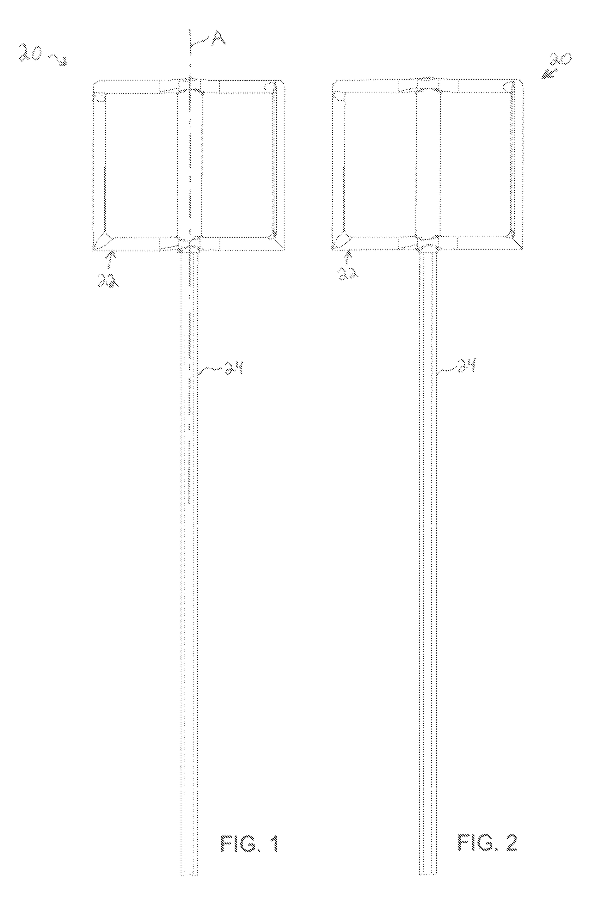
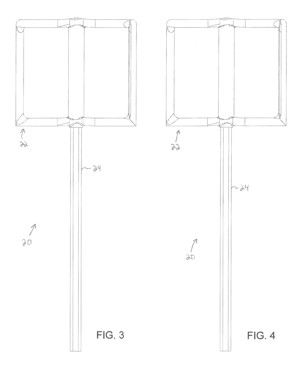
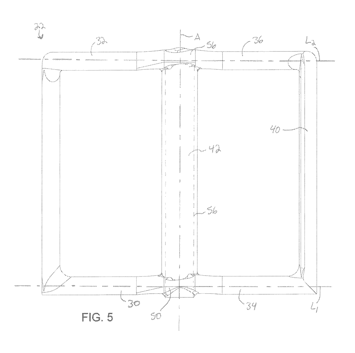
[0022]Referring now in detail to the drawings, and initially to FIGS. 1-4, a mixing device is designated generally by reference numeral 20. The mixing device 20 may include a blade 22 that extends along a longitudinal axis A and a shaft 24 fixed to the blade 22. The blade 22 may be fixed to the shaft 24, for example by a molded connection.

[0023]The shaft 24 may be concentric with the longitudinal axis A and may have a length along the longitudinal axis A that is greater than a length of the blade 22 along the longitudinal axis A. For example, drive end of the shaft 24 may extend through most of the blade 22 and a driven end of the shaft 24 opposite the drive end may extend away from the blade 22 more ...


PUM


Abstract

A mixing device including a blade with radially outwardly extending arms and / or with a longitudinally extending wall with an elliptical cross-section. The elliptical cross-section may synergistically provide enhanced mixing and enhanced durability of the blade compared to previously known joint compound mixers. For example, the elliptical cross section may provide structural support to the radially outwardly extending arms and / or the longitudinally extending walls while allowing the radially outwardly extending arms and / or the longitudinally extending walls to cut through and spread joint compound. The structural support may allow the blade to be made of a plastic material. For example, the blade may be made of acrylonitrile butadiene styrene (ABS). Making the blade out of plastic may reduce scratching and degradation of the container that holds the joint compound during mixing, compared to previously known drywall mixers made of metal.

Description

RELATED APPLICATIONS[0001]This application claims the benefit of U.S. Provisional Application No. 62 / 150,582 filed Apr. 21, 2015, which is hereby incorporated herein by reference.FIELD OF INVENTION[0002]The present invention relates generally to mixing devices, and more particularly to mixing devices for joint compound, paint, ceramic tile thin set, or epoxy coatings.BACKGROUND[0003]Joint compound (also referred to as “drywall compound”) is typically a pre-mixed paste, a mud compound, or a white powder of primarily gypsum dust mixed with water. The mud is generally applied in conjunction with paper or fiber joint tape to seal joints between sheets of drywall to create a seamless base for painting a surface formed by the drywall sheets.[0004]The joint compound often comprises a combination of many materials that need to be homogenized to ensure proper functioning of the joint compound once applied to a drywall joint. For example, the joint compound may comprise water, limestone, expa...

Claims


Application Information

Patent Timeline
Patent Type & Authority Patents(United States)
IPC IPC(8): B01F7/00B01F13/00
CPCB01F7/00033B01F13/0028B01F7/00583B01F27/053B01F27/13B01F33/50115
Inventor MORTON, RONALD J.
Owner BUDDY TOOLS
Why Eureka
Try Eureka