Liquid mixing apparatus

a technology of mixing apparatus and liquid, which is applied in the direction of transportation and packaging, rigid containers, packaging, etc., can solve the problems of unstable amount of mixture of fragrance and flowing fluid, inability to control the flow of fluid in contact with fragrance material, and increased adverse effects, etc., to facilitate the control of the amount of mixture, increase the flow rate, and facilitate the effect of reducing the amount of mixtur

Active Publication Date: 2019-03-05
AROTEC CORP
View PDF2 Cites 0 Cited by
  • Summary
  • Abstract
  • Description
  • Claims
  • Application Information

AI Technical Summary

Benefits of technology

[0008]When the apparatus is in use, the user can simply install the liquid container onto the adapter; therefore, the apparatus is facilitated for use. In addition, the liquid container is able to naturally trigger the lifting assembly to allow the first piercing member and the second piercing member of the piercing assembly to protrude out of the lifting assembly and to pierce into the liquid container; thereby allowing the first piercing member to connect to the branch passage portion and the second piercing member to connect to the return passage portion. As a result, the fluid flowing into the flowing passage portion via the fluid inlet can have a portion of the fluid flowing into the branch flow space via the branch flow opening, and it is also able to enter into the liquid container via the first piercing member in order to increase the pressure of the fluid flowing toward the liquid container. Consequently, the flow of the fluid is smooth and is able to mix with the fragrance inside the liquid container; following which it is able to exit from the fluid outlet via the second piercing member, the return flow space, the return flow opening and the flowing passage portion.
[0010]When there I a need for the flow rate of the fluid for mixing, since the structural design of the branch passage portion allows the pressure of the fluid flowing toward the liquid container to increase, the dimensions of the branch passage portion and the return passage portion can be increased under the condition of maintaining the pressurization in order to increase the flow rate. In addition, the range of increase of the dimension is relatively large. With the aforementioned technique, the drawback of the known fluid type of fragrance device can be overcome while achieving the effects of convenience use, facilitated control of amount of mixture and relatively large of variable range.

Problems solved by technology

However, through actual experiments, it is found that since there is no special structure provided to increase the fluid pressure before the direct contact between the fluid and the fragrance material, the pressure of the fluid before contacting the fragrance material is close to the pressure of the fluid after contacting the fragrance material.
As a result, the flowing pressure of fluid being controlled is insufficient such that interference occurs, leading to the drawback of improper flow of the fluid and, consequently, the drawback of unstable amount of mixture of the fragrance with the flowing fluid.
In addition, due to the issue of insufficient pressure of the flowing fluid in the known fluid type of fragrance device, the amount of the flow of the fluid in contact with the fragrance material cannot be controlled and increased.
If the amount is increased forcefully, it can lead to more adverse effect of improper fluid flow and unstable mixture amount, or the situation where a portion of the fluid is accumulated at the area of the fragrance material without flowing.
Since most of the flowing fluid actually flows out without contacting with the fragrance, the flow rate of the fluid with the use of such known fluid type of fragrance device is limited and cannot be increased effectively.

Method used


Image

  • Liquid mixing apparatus
  • Liquid mixing apparatus
  • Liquid mixing apparatus

Examples


Embodiment Construction

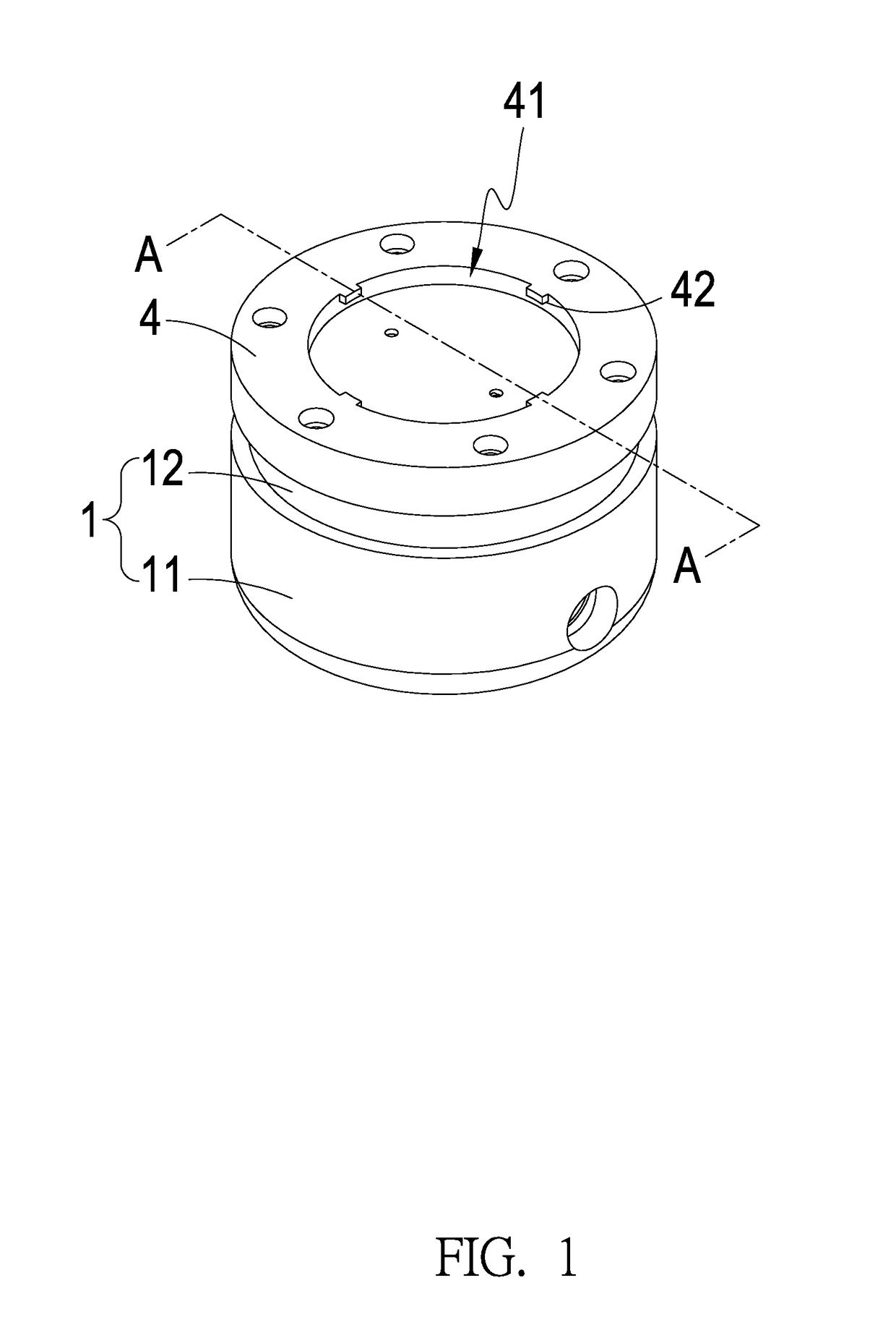
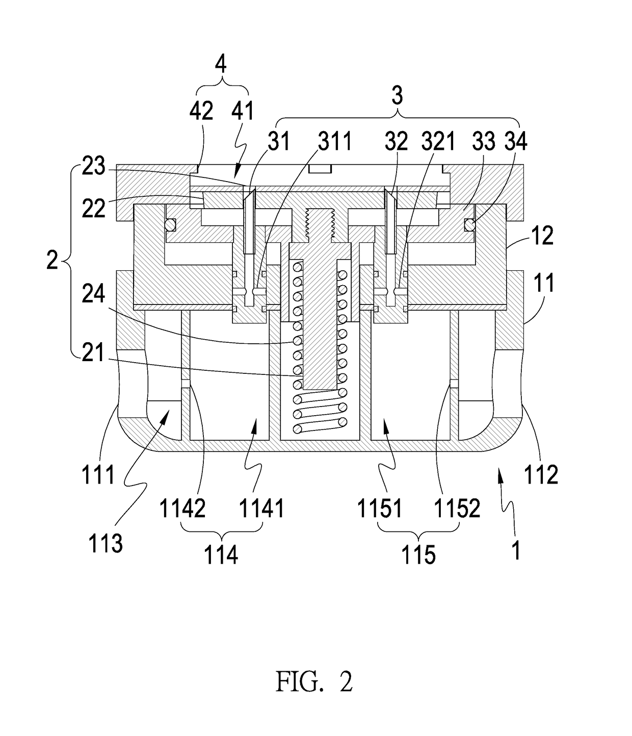
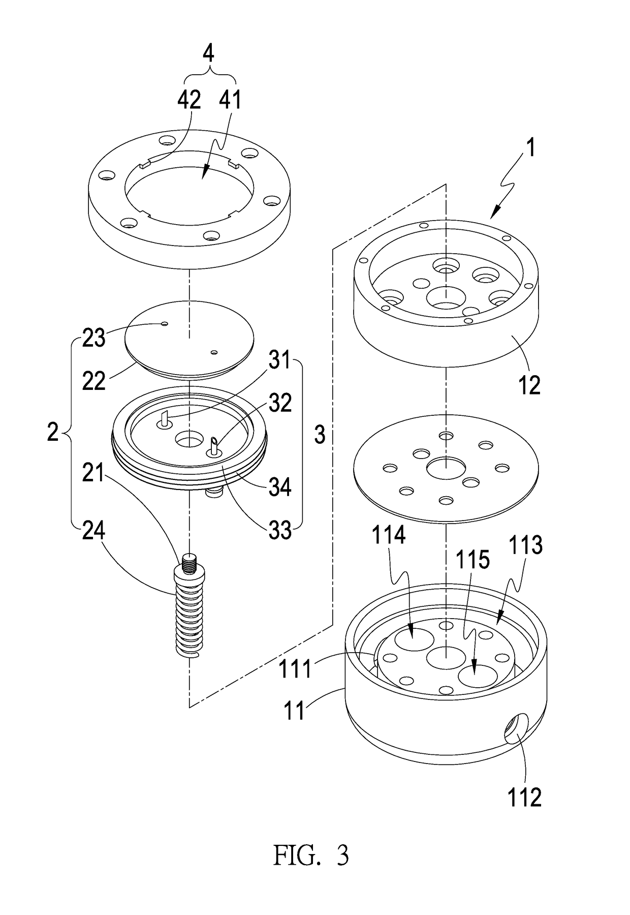
[0018]As shown in FIG. 1 to FIG. 3, the liquid mixing apparatus of the present invention mainly comprises at least one connecting device 1, at least one lifting assembly 2, at least one piercing assembly 3, at least one adapter 4; wherein the connecting device 1 includes one side formed of at least one fluid inlet 111 and another side formed of at least one fluid outlet 112. In addition the internal of the connecting device 1 is formed of at least one flowing passage portion 113 connected to the fluid inlet 111 and the fluid outlet 112. A side area of the flowing passage portion 113 inside the connecting device 1 includes at least one branch passage portion 114 connected thereto, and a side area of the flowing passage portion 113 inside the connecting device 1 includes at least one return flow portion 115 connected thereto.

[0019]The lifting assembly 2 is movably arranged on the connecting device 1. The piercing assembly 3 is movably arranged on the lifting assembly 2 and configured ...


PUM


Abstract

During the use of a liquid mixing apparatus, a liquid container can be installed onto an adapter. The liquid container drives a lifting assembly to allow a piercing assembly to pierce through the adapter. Once a fluid flows into a flowing passage portion via a fluid inlet, a portion of the fluid is pressurized via a branch passage portion with easy control and further flows into the liquid container to mix with a fragrance material inside the liquid container. The mixed fragrant liquid then flows out of a fluid outlet from the piercing assembly via the return passage portion and the flowing passage portion. With the pressurization design of the branch passage portion, the apparatus allows the increase of dimension to increase the flow rate while maintaining the pressurized liquid, which is convenient to use and facilitated for the control of the mixture amount with greater variation range.

Description

(a) TECHNICAL FIELD OF THE INVENTION[0001]The present invention is related to a liquid mixing apparatus convenient to use and facilitated to control the amount of mixture with a greater variation range.(b) DESCRIPTION OF THE PRIOR ART[0002]A known fluid type of fragrance device comprises a housing, a container space inside the housing, a channel opening formed on the housing and connected to the container space and a fragrance material received inside the container space. During the use of such known fluid type of fragrance device, the device is installed on the flowing path of the fluid used for washing or flushing, such as the installation on the (shower head) water supply pipe or (toilet) reservoir tank, in order to allow the fluid to contact with the fragrance material for mixing with each other such that fragrance can be introduced into the fluid.[0003]However, through actual experiments, it is found that since there is no special structure provided to increase the fluid pressu...

Claims


Application Information

Patent Timeline
Patent Type & Authority Patents(United States)
IPC IPC(8): B01F13/00B65D1/32
CPCB01F13/0061B65D1/32B01F13/0074B01F13/0064B01F25/316B01F35/7131B01F33/301B01F33/305B01F33/3017
Inventor WANG, CHING-HUAYEN, YU-WEN
Owner AROTEC CORP
Why Eureka
Try Eureka