Valve designed to indicate whether or not fluid is passing

a valve and fluid technology, applied in the field of storage covers, can solve the problems of the deterioration of the pump or vacuum cleaner used, and the simpleness of the valve system, so as to avoid the different deteriorations

Active Publication Date: 2019-03-05
CIE EURO
View PDF10 Cites 0 Cited by
  • Summary
  • Abstract
  • Description
  • Claims
  • Application Information

AI Technical Summary

Benefits of technology

[0018]The object of the present invention is to contribute a simple and effective solution to the aforementioned problems among other problems; the constraints connected to costs and to manufacture being quite obviously taken into consideration within the framework of the present invention.
[0019]One of the technical problems resolved by the object of the present invention therefore consists of proposing a solution aiming to improve pumping or aspiration; this simple, easy to use, esthetic and fun solution, proposing a valve taking into account the constraints of light weight, toughness and fluid-tightness connected with bulk reduction of the objects contained within the cover.
[0032]The valve according to the present invention therefore allows control and checking of the pumping or of the aspiration in an intuitive manner so as to avoid any deterioration of the pumping or aspiration means caused by prolonged and excessively long use of said means.
[0039]The user of such a valve according to the present invention will therefore be able to intuitively determine whether the fluid pumping operation is effective or not by looking to see whether or not the signaling means indicates that fluid is passing.
[0045]The user of such a valve according to the present invention will therefore be able to intuitively determine whether or not the fluid pumping operation is effective by looking to see whether or not the signaling means indicates that fluid is passing.
[0057]Thus, the object of the present invention, by its different functional aspects and its advantageous features, corrects the different disadvantages noted in the prior art by allowing control of pumping or aspiration and thus avoiding the different deteriorations noted with valve systems identified in the prior art.

Problems solved by technology

It has been observed by the applicant that certain disadvantages result from the simplicity of these valve systems.
Indeed when, during pumping, a vacuum is created inside the cover, and the user continues to pump, the pump or vacuum cleaner, and its components in particular, deteriorates.
More precisely, in this case, the pump or vacuum cleaner is pumping vacuum, which can cause deterioration of the pump or the vacuum cleaner that is used.
It is also possible that the structure of the cover will tear if the material constituting it is not strong enough, and pumping continues for an extended period.
It is therefore noted that the valves known in the prior art do not offer a satisfactory solution suited to this type of use.

Method used


Image

  • Valve designed to indicate whether or not fluid is passing
  • Valve designed to indicate whether or not fluid is passing
  • Valve designed to indicate whether or not fluid is passing

Examples


Embodiment Construction

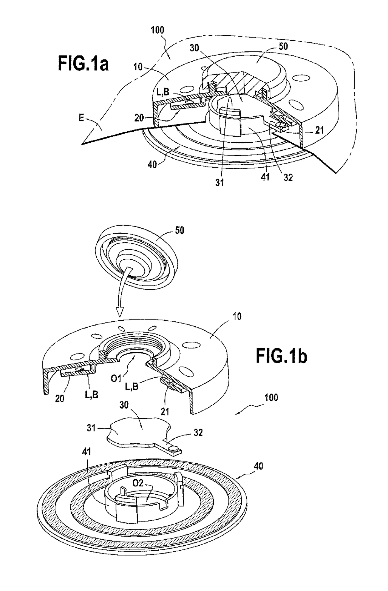
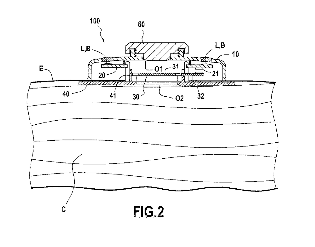
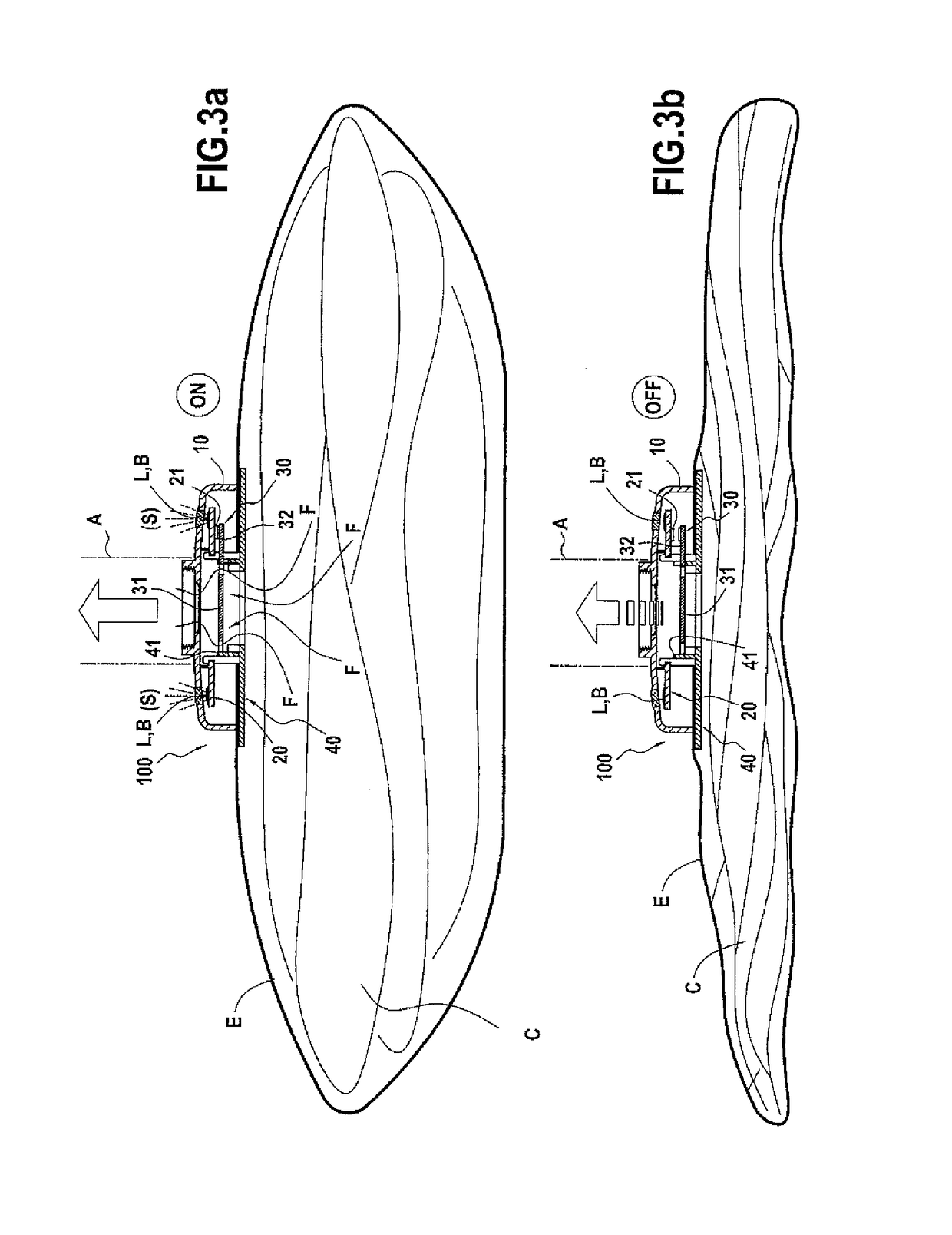
[0064]A valve and a storage cover conforming to a particular embodiment of the present invention will now be described in what follows with reference jointly to FIGS. 1 through 3a-3b.

[0065]As a reminder, as mentioned previously, it has been observed in the prior art that the pumping of air contained in storage covers for the purpose of compression and storage of at least one textile article can be the cause of deterioration of the pumping equipment.

[0066]Indeed, when pumping or aspiration is continued when maximum compression of the article has already been attained, the different components of the pumping equipment can be deteriorated; furthermore, it is useless to continue pumping in a vacuum.

[0067]One of the objectives sought by the object of the present invention is to allow the user of the pump or the vacuum cleaner to be warned that, during compression, the storage cover is emptied of its air.

[0068]First of all it is recalled that the term pumping equipment must be understood...


PUM


Abstract

The subject of the present invention is a valve for extracting, by pumping, a fluid contained in a space, said valve comprising: a) a main body having a first opening for the passage of said fluid during pumping, and b) an indicator means configured to indicate whether or not the fluid is passing through the first opening.

Description

CROSS REFERENCE TO RELATED APPLICATION[0001]This is a 371 national phase application of International Application No. PCT / FR2010 / 050989, filed May 21, 2010, the content of which is incorporated herein by reference in its entirety.TECHNICAL FIELD[0002]The object of the present invention relates to the field of containers for storing and / or transportation of articles; the object of the present invention relates more particularly to storage covers designed for storing and / or transporting bulky compressible articles such as for example textile articles (comforters, pillowcases, clothing, outdoor furniture cushions, etc.) while reducing their bulk volume.[0003]The object of the present invention relates more precisely to the field of valves specially designed for such containers or such storage covers.[0004]What is meant by valve in all of the present description that follows is any type of device that a) provides, in its closed position, a perfect fluid-tight seal for a container such a...

Claims


Application Information

Patent Timeline
Patent Type & Authority Patents(United States)
IPC IPC(8): B65D81/20F16K37/00F16K15/20F16K51/02
CPCB65D81/2038B65D81/2023F16K15/20F16K37/0058F16K51/02Y10T137/86083Y10T137/7903Y10T137/7908Y10T137/8225Y10T137/8326
Inventor EPICUREO, GIULIOLIU, CHUN CHI
Owner CIE EURO
Why Eureka
Try Eureka