Locking device

a technology of locking device and sealing mechanism, which is applied in the direction of building locks, wing fasteners, building components, etc., can solve the problems of increasing the cost and complexity of locking apparatus, modern locks potentially working at the very edge of their performance capability, and reducing the effectiveness of locking and sealing mechanisms, so as to improve the effectiveness of locking and sealing. , the effect of tight manufacturing tolerances

Inactive Publication Date: 2019-03-05
EINSTEIN IP
View PDF22 Cites 7 Cited by
  • Summary
  • Abstract
  • Description
  • Claims
  • Application Information

AI Technical Summary

Benefits of technology

[0008]The cam provides improved locking over prior art locks discussed above. The cam acts as a blocking device imparting a resistance to the opening of the leaf when the cam is in the locked condition through contact with the cam engaging surface on the leaf or the frame. This enhances locking compression and / or sealing of the leaf. Furthermore, as the plane of rotation of the cam is perpendicular to the plane of the leaf, the cam can be arranged such that exertion of a pushing force on the trailing face of the leaf to open it from a closed position will urge the cam in the direction of the locking condition, thus increasing sealing performance as the load on the leaf increases. As will be further explained below, a seal can be incorporated on the cam or on the cam engaging surface that the cam comes into contact with, therefore providing sealing or improved sealing for the door when the cam is in the locked condition. Where the cam is installed at the bottom edge of a leaf, the cam can be fully housed in a recess that is recessed such that its opening is flush with the floor, such that the device provides sealing at the bottom edge of the leaf, but without raising the threshold above the surrounding floor level.
[0009]In one embodiment the cam protrudes into the path of swing of the leaf or part of the leaf when the cam is in the in the locked condition. Suitably the trailing face of the leaf may be the outer face of the leaf, the leaf having an inner and an outer face. Suitably the locking device may be for a leaf for closing an aperture in a wall of a chamber, such as the external wall of a building, the leaf being pivotally mounted relative to the wall to swing inwardly in the direction of the inner surface of the leaf in order to open the leaf, and to swing in the opposite direction to close the leaf. The locking device is mountable so as to prevent the leaf from swinging inwardly from the closed position to an open position when the locking device is in the locked condition.
[0014]Preferably the device is adapted such that when the or each cam is in the locked condition, the exertion of a leaf opening force on the trailing face of the leaf forms a seal, or enhances a seal between the leaf and the frame. Suitably this prevents the ingress of fluid, air-borne particles, heat or pressure between the leaf and the frame. Said leaf opening force may be a pushing force on the trailing face of the door. The seal may be formed between the cam and the leaf or the action of the cam due to the leaf opening force improving a seal between the leaf and the frame. The device may include suitable sealing means. For example, a seal can be incorporated on the cam or on the cam engaging surface that the cam comes into contact with. The locking device can act as the main seal for a leaf assembly, through tight manufacturing tolerances or by inclusion of a soft seal integral with the cam or cam engaging surface.
[0015]Preferably the device is adapted such that when the or each cam is in the locked condition, the exertion of a leaf opening force on the trailing face of the leaf urges the cam to rotate in the direction of the locked condition. The cam is mountable relative to the leaf such that a leaf opening force, such as a pushing force exerted on the trailing face of the door, will increase the effectiveness of the locking, rather than decrease as is the case for typical prior art locks.
[0020]Preferably the device further comprises actuating means for rotating the or each cam from the unlocked to the locked condition. The cam may therefore be operated without the need for the user to manually move the lever portion directly. The actuating means can be operated remotely, without requiring direct access to the actuating means, such that a user on either side of the leaf can cause the cam to move between the locked and unlocked conditions. The locking device may comprise control means for controlling the actuating means. The control means may be remote from the actuating means. For example, the control means may be displaced from the actuating means such that the control means are easily accessible by the user. The control means may comprise a control means on both the leading face of the leaf and a control means on the trailing face of the leaf so that a user on either side of the leaf can cause the cam to move between the locked and unlocked conditions.
[0024]Preferably the or each cam is elongate. The elongate cam has a longitudinal axis, the cam being mountable with its longitudinal axis parallel with the edge of the leaf that the cam is mountable at. An elongate cam provides continuous sealing along the length of the cam when the cam is in the locked condition. Use of an elongate cam furthermore provides improved locking over prior art locks, such as bolts, that are subject to intense point loading, making the lock only as strong as the leaf or the frame it engages with.

Problems solved by technology

In these cases the operation of the locking and sealing mechanisms may be very complex using worm gears, bevel gears, ratchets or other highly mechanised means.
In some cases this operation may be aided by electronic means although this inevitably increases the cost and complexity of the locking apparatus significantly.
This is despite the fact that the opening direction of the door is not at all advantageous as these forces will in effect be opening up the seal.
This results in modern locks potentially working at the very edge of their performance capability and presents the risk of catastrophic failure.
With adjustable locks these may be tightened up to provide good compression against the forces trying to open the door or gate, however because of the load required to be applied through the handle or other means in which to operate the locks, the forces required to activate the locks may be beyond that provided in building or other regulation in some cases making it inoperable to many users.
It will also potentially damage the soft seals through crushing, damage hinges or other elements through hyper-extending, and will still be vulnerable to catastrophic failure though failure of a fixing or snapping of a lock component.
Handle forces required for operation and the sealing pressure required may be inextricably linked and induce an inherent weakness into the system.

Method used


Image

  • Locking device
  • Locking device
  • Locking device

Examples


Embodiment Construction

[0046]The present embodiments represent currently the best ways known to the applicant of putting the invention into practice. But they are not the only ways in which this can be achieved. They are illustrated, and they will now be described, by way of example only.

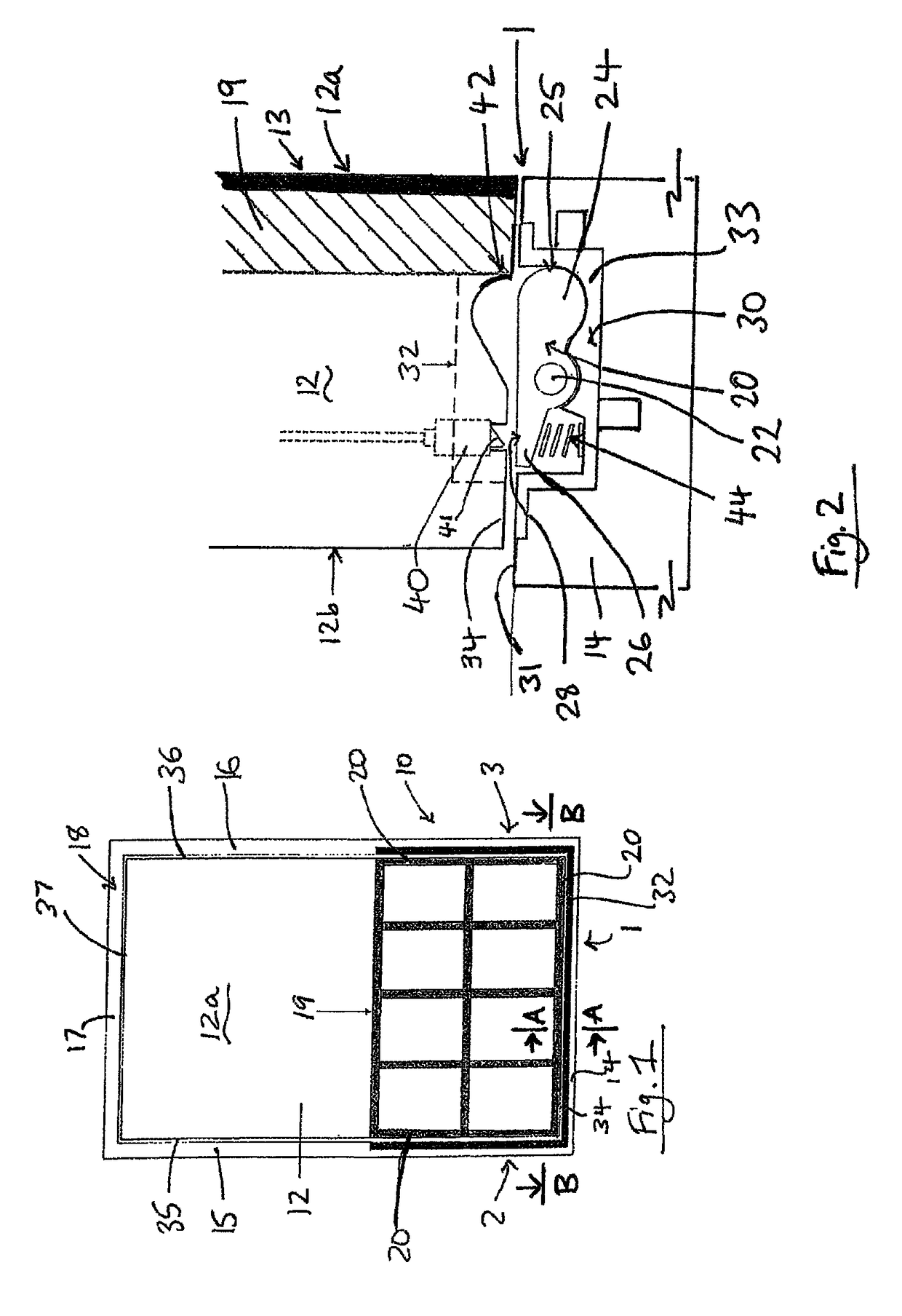
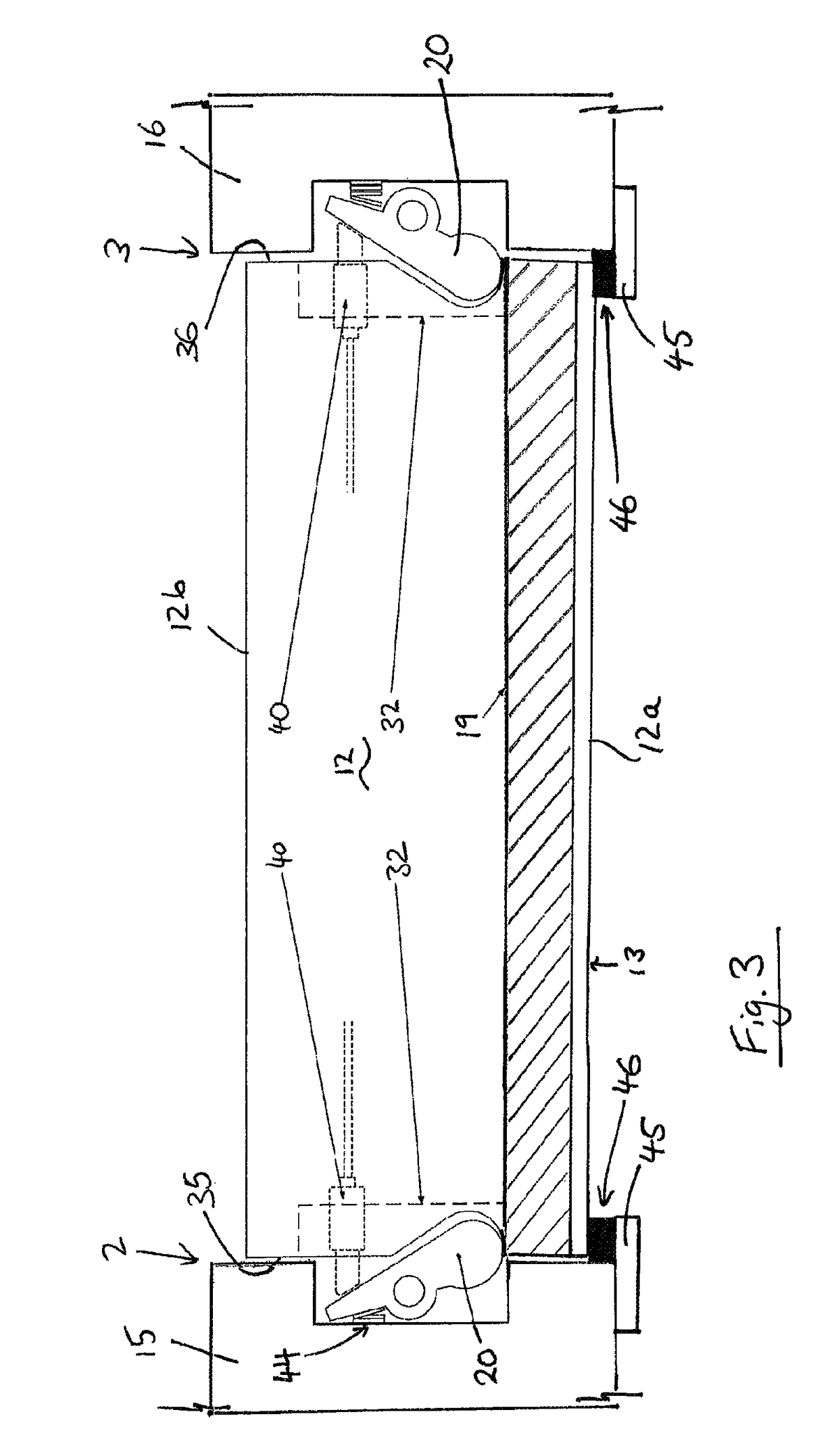
[0047]Referring to FIG. 1, this diagrammatically shows a locking device 10 installed in a leaf assembly comprising a leaf 12 mounted in a corresponding frame 18, also known as a jamb. In this embodiment the leaf 12 is a moveable leaf and the frame 18 is fixed. The leaf can be any leaf, such as a door or gate, suitable for closing an aperture within the frame.

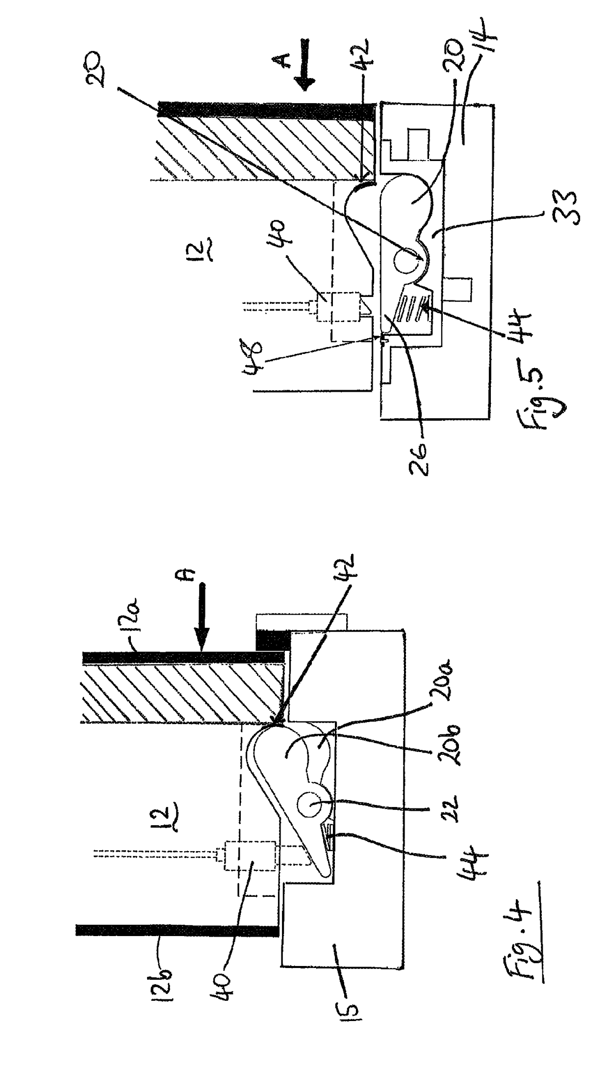
[0048]The locking device comprises a cam 20, which acts as a blocking member to resist movement of the leaf 12. The cam 20 is moveable between an unlocked condition in which it does not hinder the movement of the leaf 12 and a locked condition in which it resists the movement of the leaf 12, as will be further described below. The locking device includes an actuator m...


PUM


Abstract

A locking device for a leaf pivotally mounted in a frame, the leaf having a leading face, a trailing face, a bottom edge and side edges, and being pivotally moveable relative to the frame between an open position and a closed position, the locking device comprising at least a first cam rotatable between an unlocked condition and a locked condition, the plane of rotation of the cam being perpendicular to the plane of the leaf when in the closed position, wherein in the locked condition the cam is engageable with a cam engaging surface on the leaf or the frame, engagement of the cam with the cam engaging surface preventing the leaf from moving away from the closed position.

Description

CROSS REFERENCE TO RELATED APPLICATION[0001]The present application is the U.S. national stage application of International Application PCT / GB2014 / 053505, filed Nov. 26, 2014, which international application was published on Jun. 4, 2015 as International Publication WO 2015 / 079228. The International Application claims priority of Great Britain Patent Application 1320870.7, filed Nov. 26, 2013.FIELD OF THE INVENTION[0002]The present invention relates to a locking device for a leaf pivotally mounted in a frame. The invention also relates to a leaf assembly comprising a leaf mounted in a frame and a locking device therefor.BACKGROUND TO THE INVENTION[0003]Locks for doors, windows and gates come in many forms from simple sliding bolts or rotating catches to modern multi-point locks including hooks, or cam rollers. Whilst the technology for locks has improved, the demands on doors have increased markedly. Doors are expected to not just close an aperture but are now expected to prevent de...

Claims


Application Information

Patent Timeline
Patent Type & Authority Patents(United States)
IPC IPC(8): E06B5/10E05C19/00E05B63/00E05B63/24E06B7/16E06B7/22E06B9/00
CPCE05C19/002E05B63/0052E05B63/242E06B7/16E06B7/22E06B9/00E06B5/10E06B2009/007E05B17/0025E05B65/001
Inventor WARD, NICHOLASCLEGG, BRIAN
Owner EINSTEIN IP
Why Eureka
Try Eureka