Furniture hinge

a technology for furniture and hinges, applied in the field of furniture hinges, can solve the problems of increased installation space and additional installation effort, and achieve the effect of compact structur

Active Publication Date: 2019-03-05
JULIUS BLUM GMBH
View PDF47 Cites 7 Cited by
  • Summary
  • Abstract
  • Description
  • Claims
  • Application Information

AI Technical Summary

Benefits of technology

[0004]It is an object of the present invention to provide a furniture hinge of

Problems solved by technology

However, the additional arrangement of such a closing mechanism would resul

Method used


Image

  • Furniture hinge
  • Furniture hinge
  • Furniture hinge

Examples


Embodiment Construction

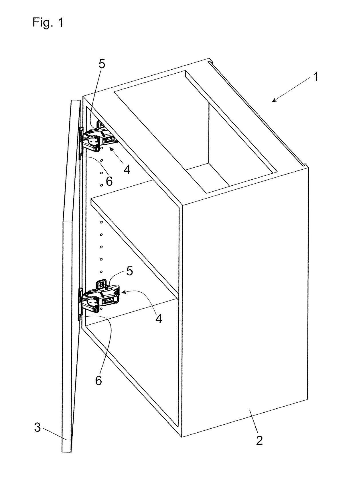
[0017]FIG. 1 shows an item of furniture 1 with a furniture carcass 2 in a perspective view, wherein a movable furniture part 3 in the form of a door is pivotally supported about a verticallyextending axis relative to the furniture carcass 2 by furniture hinges 4. The furniture hinges 4 each have a first fastening portion 5 with a hinge arm 5a (FIG. 2a) to be fixed to the furniture carcass 2 and a second fastening portion 6 with a hinge cup 6a (FIG. 2a) to be fixed to the movable furniture part 3. The hinge cup 6a, as commonly known, can be countersunk in a cylindrical bore provided in the movable furniture part 3, and is pivotally connected to the first fastening portion 5 by a joint mechanism.

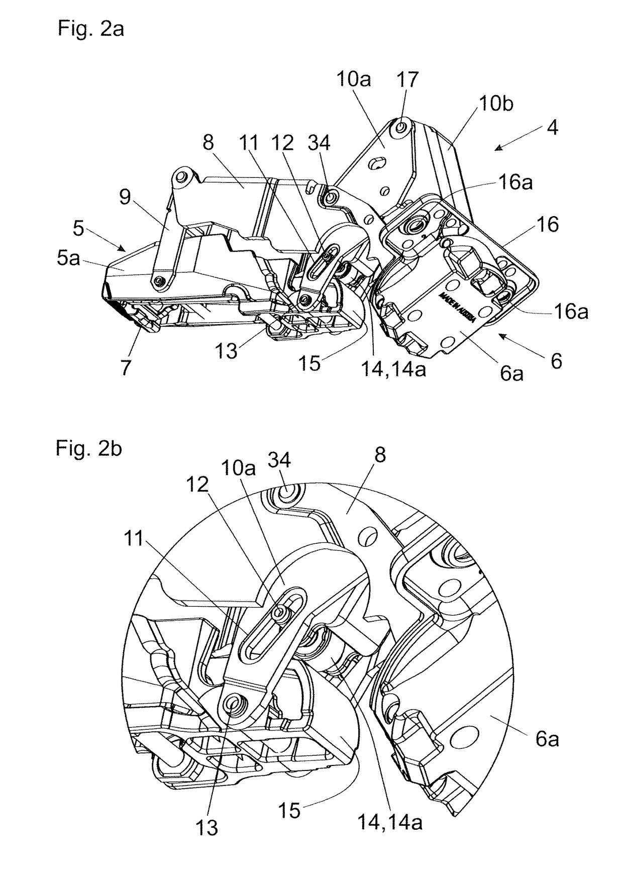
[0018]FIG. 2a shows the furniture hinge 4 in a perspective view. The furniture hinge 4 includes a first fastening portion 5 with a hinge arm 5a which can be releasably latched by a spring-loaded latching lever 7 onto a mounting plate to be fixed to the furniture carcass 2. A second fastening p...


PUM


Abstract

A furniture hinge for pivotally connecting at least two furniture parts to one another includes at least two fastening portions pivotally connected to one another for fastening to the furniture parts, and the fastening portions can be moved relative to each other between a closed position and an open position. A spring device presses the fastening portions into the closed position and/or into the open position, and a damping device dampens a relative movement of the fastening portions. The spring device is integrated into the damping device, and the damping device and the spring device are accommodated within a first and within a second housing portion. The first and second housing portions are displaceably arranged relative to one another for performing the relative movement.

Description

BACKGROUND OF THE INVENTION[0001]The present invention relates to a furniture hinge for pivotally connecting at least two furniture parts to one another. The furniture hinge includes at least two fastening portions pivotally connected to one another for fastening to the furniture parts, wherein the fastening portions can be moved relative to each other between a closed position and an open position. The furniture hinge also includes a spring device for pressing the fastening portions into the closed position and / or into the open position, and a damping device for dampening a relative movement of the fastening portions, wherein the spring device is integrated into the damping device.[0002]WO 2010 / 124946 A1 shows a damping device for furniture hinges, wherein a piston is displaceably arranged within an inner space of a housing. For applying a pressure to the piston, a piston rod is provided which protrudes out of the housing and which is coupled via a connecting element to a hinge pin...

Claims


Application Information

Patent Timeline
IPC IPC(8): E05D3/14E05D3/16E05D11/10E05F5/00E05F1/12E05D3/06E05F1/08E05D15/58
CPCE05D3/142E05D3/16E05D11/1021E05F1/1253E05F5/006E05D3/06E05Y2900/20E05D11/10E05D15/58E05F1/08E05Y2600/46E05Y2800/205E05Y2800/24E05D3/14E05D7/086E05F3/04E05F3/20
Inventor HAMMERER, ANDRE
Owner JULIUS BLUM GMBH
Why Eureka
Try Eureka