Tailgate with reversing camera

Active Publication Date: 2019-03-12
GM GLOBAL TECH OPERATIONS LLC
6 Cites 2 Cited by

AI-Extracted Technical Summary

Problems solved by technology

However, this upper edge also has a high tendency for getting dirty for swirled-up dust and dirt that settles on the tailgate.
In addition, rain has a tendency to flushed dust off the steep regions of the tailgate which settles on the less steep regions, specifically the upper edge where protrusions of the camera arrangement are directed downwards.
Such a protrusion is formed by a cover which has to be folded open for extending the camera but is at risk of sticking through adhering dirt.
Since the dirty rain water does not flow u...

Method used

[0025]A middle portion of the channel 11 is concealed behind a cover 13. The cross-sectional contour of the cover 13 follows that of the channel 11, so that both together delimit a contiguous recessed grip 14 that is open towards the bottom extending over the entire length of the channel 11. Since the recessed grip ...

Benefits of technology

[0006]In accordance with the present disclosure, a tailgate for a vehicle is provided with an outer skin and a grip recessed into the outer skin, which is open towards the bottom with the tailgate in the closed position. A wall of the recessed grip is formed at least in part by a cover of an extendable mounting of the camera. Being part of the wall of the recessed grip, the cover is protected from dirt flushed along by dirty rain water, which might cause sticki...

Abstract

A tailgate for a vehicle includes an outer skin and a grip recessed into the outer skin, which open towards the bottom when the tailgate in a closed position. A wall of the recessed grip is formed at least in part by a cover of an extendable mounting for a camera. The camera is positionable between a retracted position in which the cover conceals the camera and an extended position in which the camera provides a field of view behind the vehicle.

Application Domain

Technology Topic

Image

  • Tailgate with reversing camera
  • Tailgate with reversing camera
  • Tailgate with reversing camera

Examples

  • Experimental program(1)

Example

[0021]The following detailed description is merely exemplary in nature and is not intended to limit the invention or the application and uses of the invention. Furthermore, there is no intention to be bound by any theory presented in the preceding background of the invention or the following detailed description.
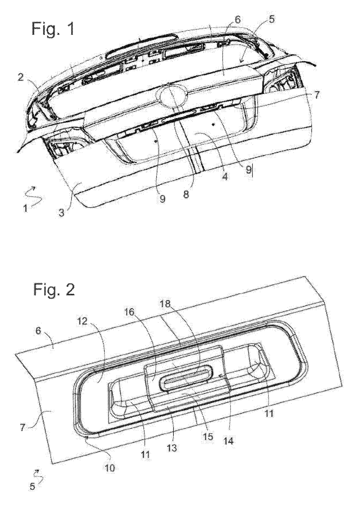
[0022]FIG. 1 shows a tailgate 1 for a motor vehicle in wagon design. The upper part of the tailgate 1 is formed by a large window frame 2. In an outer panel 3 forming the lower part of the tailgate 1, a central indentation 4 for a number plate is formed. An outer skin element 5 facing the outer panel 3 has an angular cross section with an upper leg 6, which downwards adjoins the window frame 2. The outer skin element 5 joins the outer panel 3 on lateral ends on both sides of the central indentation 4 in a flush manner. A lower leg 7 of the outer skin element 5 forms an upper edge of the indentation 3 and in the closed position of the tailgate 1 is orientated approximately horizontally. From the perspective of a user standing in front of the tailgate 1 in order to open it, the lower leg 7 is not visible. Alternatively, the leg 7 can also be a unitary part of the outer panel 3.
[0023]Three openings of the leg 7 are visible in FIG. 1, a central opening 8 and two openings 9 on the left and right of the central opening which are mirrored relative to one another. The openings 9 are provided in order to receive lamps for illuminating a number plate mounted in the recess 4. The central opening 8 is provided in order to receive a camera assembly described in detail by way of the following figures.
[0024]FIG. 2 shows an extract of the leg 7 from a perspective obliquely from below. In the opening 8, a molding 10 made of plastic is recessed. It includes a central channel 11 which in the closed position of the tailgate 1 is open towards the bottom and a flange 12 surrounding the channel 11, which all around the opening 8 lies against the leg 7.
[0025]A middle portion of the channel 11 is concealed behind a cover 13. The cross-sectional contour of the cover 13 follows that of the channel 11, so that both together delimit a contiguous recessed grip 14 that is open towards the bottom extending over the entire length of the channel 11. Since the recessed grip 14 crosses the middle plane of the tailgate 1 and can extend on both sides of the middle plane over a large part of the width of the indentation 4 as far as into the vicinity of the openings 9, the recessed grip 14 can be easily and securely found by a user even when the leg 7 is concealed from his viewing direction.
[0026]The cover 13, in the exemplary embodiment considered here, extends only over approximately a third of the length of the channel 11. However, it is possible to widen the same so that it completely covers the channel 11 or even the flange 12.
[0027]Like the channel 11, the cover 13 has a roof-like or peaked cross section that is more clearly noticeable in FIG. 3 with a steep flank 15 on its side facing the indentation 4 or the vehicle interior and a shallow or flatter flank 16 on its side facing the leg 6. The flank 16 is orientated approximately perpendicularly to the direction of the pulling force which the user exerts for opening the tailgate 1, thus facilitating exerting said force. In the position shown in FIG. 2, the cover 13 closes a shaft 17 of the molding 10.
[0028]A part of the flange 16 is taken up by a pushbutton 18. This pushbutton 18 actuates an electrical switch 19, which together with a camera 20 is mounted in a mounting 21 (see FIGS. 4, 7), of which the cover 13 is a part. A signal of the switch 19 controls the unlocking of a lock which is not shown in the figures and known per se on the lower edge of the tailgate 1, so that when the user reaches into the recessed grip 14 in order to lift the tailgate 1, he or she simultaneously activates the switch 19 and the lock is unlocked. According to a version, the entire cover 13 could serve as pushbutton 18.
[0029]The mounting 21 is extendable into an open position out of the shaft 17 downwards, which position is shown in FIGS. 4 and 5. In the extended position, the camera 20 has clear vision obliquely downwards of the road located below the vehicle and any obstacles behind the vehicle. Since the optical axis of the camera 20 slopes downwards towards the back, the camera 20 can be mounted in the mounting 21 closely adjacently to the flank 16 sloping in the same manner.
[0030]FIG. 6 shows an extract of the outer skin element 5 and the camera assembly mounted thereon in a view from the direction of the vehicle interior. Clearly visible are the channel 11 and an approximately cuboid housing 22 delimiting the shaft 17, which housing 22 projects from a middle section of the channel 11 through the opening 8 into the interior of the tailgate 1. In a side wall 23 of the housing 22 facing the beholder, three elongated recesses 24, 24, 25 are formed. Through the middle recess 25, signal cables 26, 27 run to the switch 19 and to the camera 20. In the two lateral recesses 24, latching projections 28 of the mounting 21 engaging from the shaft 17 are visible. Latching projections of the mounting 21, mirrored regarding the latter, also engage in recesses 24 in a side wall of the housing 22 facing away from the beholder or facing the leg 6.
[0031]In an angle between the channel 11 and the housing 22, an electric motor 29 is mounted. A housing of a gear 30 is fastened on face ends of the electric motor 29 and of the housing 22 facing away from the channel 11. It includes two intermeshing gear wheels of which one is fastened to an output shaft of the motor 29 and the other one includes an internal thread and is rotatable about a threaded rod 31 (see FIG. 7) fastened to the mounting 21 thus converting a rotation of the motor 29 into a translation of the threaded rod 31 and of the mounting 21.
[0032]FIG. 7 shows the outer skin element 5 and the various components of the camera assembly mounted thereon in an expanded representation. The pushbutton 18, the switch 19 and the signal cable 26 form a first assembly 34 which is provided in order to be mounted in a window 35 of the cover 13. The pushbutton 18 is smaller than the window 35, the gap between the pushbutton 18 and the edge of the window 35 can be filled out by a flexible seal which annularly extends about the pushbutton 18 and is fastened to the edge of the window 35 in a dirt and water-proof manner; in the representation of FIGS. 3 and 5, the seal 36 fills out the entire window 35 and covers the pushbutton 18. A lug 37, which projects from the edge towards the middle of the window 35 of the cover 13, is provided in order to mount the switch 19 on its bottom side.
[0033]The cover 13 and a guide part 38 together form the mounting 21. The guide part 38 includes a frame 39 which is curved complimentarily to the cover 13 and on which the cover 13 can be fastened in close contact for example by gluing or latching and two guide plates 41 standing away from the frame 39 on both sides of an opening 40 receiving the switch 19 and the lug 37. Between the guide blades 41 a carrier plate 42 for the fastening of the camera 20 is located. On the edges of the guide blades 41, elastic lugs 43 are cut free, the tips of which form the mentioned latching projections 28 engaging into the recesses 24. The latching projections 28 are provided with oblique flanks 44 on their side facing away from the cover 13 so that the lugs 33 when the mounting 21 is inserted in the shaft 17 of the molding 9 yield towards the center of the shaft 17 and, as soon as the latching projections 28 overlap with the recesses, again relax by engaging into these.
[0034]On the gear 30, the threaded rod 31 is visible which, when electric motor 29 and gear 30 are mounted on the housing 22, engages through a hole 35 in its front wall in the shaft 17 where it is fastened to the guide part 38.
[0035]Since the electric motor 29 and gear 30 do not protrude over the edges of the channel 10, the complete camera assembly consisting of molding 9, mounting 21, switch assembly 34 and camera 20 can be introduced from below into the opening 8 in a linear movement. In the process, two threaded rods 46 standing away from the flange 12 of the molding 9 engage in small openings 47 on both sides of the opening 8 of the outer skin element 5.
[0036]On the leg 7 of the outer skin element 5, an indentation 32 is stamped around the opening 8, which receives the flange 12 and a sealing ring 33 inserted between the flange 12 and the leg 7. With the help of nuts 48 screwed onto the threaded rods 46 the camera assembly is fastened to the leg 7 and the sealing ring 33 is compressed between the flange 12 and the leg 7.
[0037]While at least one exemplary embodiment has been presented in the foregoing detailed description, it should be appreciated that a vast number of variations exist. It should also be appreciated that the exemplary embodiment or exemplary embodiments are only examples, and are not intended to limit the scope, applicability, or configuration of the invention in any way. Rather, the foregoing detailed description will provide those skilled in the art with a convenient road map for implementing an exemplary embodiment, it being understood that various changes may be made in the function and arrangement of elements described in an exemplary embodiment without departing from the scope of the invention as set forth in the appended claims and their legal equivalents.

PUM

no PUM

Description & Claims & Application Information

We can also present the details of the Description, Claims and Application information to help users get a comprehensive understanding of the technical details of the patent, such as background art, summary of invention, brief description of drawings, description of embodiments, and other original content. On the other hand, users can also determine the specific scope of protection of the technology through the list of claims; as well as understand the changes in the life cycle of the technology with the presentation of the patent timeline. Login to view more.

Similar technology patents

Control circuit and control method

InactiveUS20060200631A1Low probabilityLess amount of hardwareMemory systemsData bufferCache miss
Owner:MITSUBISHI ELECTRIC CORP

Light-receiving element and display device

ActiveUS20090159893A1Enlarge regionLow probabilitySolid-state devicesOpticsDisplay deviceSemiconductor
Owner:JAPAN DISPLAY WEST

Method for generating identification numbers

InactiveUS6991176B1Low probabilityUser identity/authority verificationCoding/ciphering apparatusPersonal identification numberComputer hardware
Owner:DEUTSCHE TELEKOM AG

Methods for diagnosing zika virus

InactiveUS10210955B1Low probabilityImage enhancementImage analysisHigh probabilityLow correlation
Owner:ARSH BANERJEE

Classification and recommendation of technical efficacy words

People also interested in

Why Eureka
Try Eureka