Valve arrangement

a valve arrangement and valve actuation technology, applied in the direction of non-mechanical valves, oscillatory slide valves, machines/engines, etc., can solve the problems of reducing the increasing the energy loss and over-expansion reaches sub-atmospheric pressure, so as to increase the reliability of engine start-up, reduce the need for valve actuating means for starting the vehicle, and increase the energy efficiency of the cylinder arrangemen

Active Publication Date: 2019-03-19
VOLVO TRUCK CORP
View PDF15 Cites 0 Cited by
  • Summary
  • Abstract
  • Description
  • Claims
  • Application Information

AI Technical Summary

Benefits of technology

[0013]The present invention is based on the insight that by combining a check valve and an intake valve means, a simple valve arrangement is provided which is controlled such that only a desired amount of gas is provided into the cylinder of which the valve arrangement is provided to. Hereby, when the check valve is arranged in an open state, the intake valve means can be controlled for closing the intake side valve at a desired point in time. Accordingly, an advantage of the present invention is that the amount of gas provided into the cylinder, especially at low loads, can be controlled such that too much over-expansion is avoided. Hence, energy losses are reduced and the power efficiency of the cylinder which the valve arrangement is provided to is increased. Hereby, a variable Miller stroke of the cylinder is provided. Furthermore, another problem which is mitigated with the present invention is that excessive expansion is reduced. An excessive expansion cools the exhaust temperature which may create a problem for vehicle after treatment systems.
[0014]Moreover, another advantage of using the above check valve is that the need of valve actuating means for starting the vehicle is reduced, since the valve will be arranged in an open / closed position by means of the pressure it is exposed to.
[0015]Hence, the check valve provides for a “fail safe mode” when starting the engine at situations where otherwise an actuating means may fail to function. Hence, the check valve increases the reliability for start-up of the engine.
[0016]According to an example embodiment, the check valve may be a reed valve.
[0017]A reed valve should be understood as a specific type of check valve. The reed valve has at least one plate, or blade, which provides the valve in an open state when the plate / blade is exposed to pressure from a first side and in a closed state when the plate / blade is exposed to pressure from its other side. More specifically, the reed valve is normally, when not exposed to any pressure, in a closed state. When providing the reed valve at an intake side, the plate / blade of the reed valve is arranged to provide the reed valve in an open state when gas is provided into the cylinder and closed when gas is provided out from the cylinder.
[0018]An advantage of using a reed valve is that the reed valve can be positioned in an open state by means of a relatively low backpressure from the cylinder. This is advantageous since the backpressure in the cylinder generally generates pumping losses, i.e. energy losses. Accordingly, using a reed valve will thus further increase the energy efficiency of the cylinder arrangement. Furthermore, a reed valve is compact in its configuration which is an important aspect of cylinders since it can further reduce dead volumes in the cylinder. Another advantage is that a reed valve has a relatively low force of inertia which makes the opening / closing of the valve a fast process. Hence, the reed valve can quickly turn from an open state to a closed state, and vice versa.

Problems solved by technology

A problem with a two-stage engine is that they are too over-expanded at low loads, which means that there is too much intercooled air, or other type of gas, added to the combustion cylinder, which results in that the over-expansion reaches sub atmospheric pressure.
Hereby, the efficiency of the cylinder arrangement reduced since sub atmospheric pressure will create energy losses.
Also, it is a problem that a lot of air needs to be pumped at low loads, which thus further tends to increase the energy losses of the cylinder arrangement.
An excessive expansion cools the exhaust temperature which may create a problem for vehicle after treatment systems.

Method used


Image

  • Valve arrangement
  • Valve arrangement
  • Valve arrangement

Examples


Embodiment Construction

[0051]The present invention will now be described more fully hereinafter with reference to the accompanying drawings, in which exemplary embodiments of the invention are shown. The invention may, however, be embodied in many different forms and should not be construed as limited to the embodiments set forth herein; rather, the embodiments are provided for thoroughness and completeness. Like reference characters refer to like elements throughout the description.

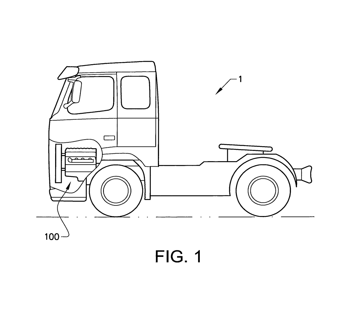
[0052]With particular reference to FIG. 1, there is provided a vehicle 1 with an internal combustion engine arrangement 100 provided with a valve arrangement 101, 201, 301 (see FIGS. 3-8) according to the present invention. The vehicle 1 depicted in FIG. 1 is a truck for which the inventive intern& combustion engine arrangement 100 and the valve arrangement 101, 201, 301, which will be described in detail below, is particularly suitable for.

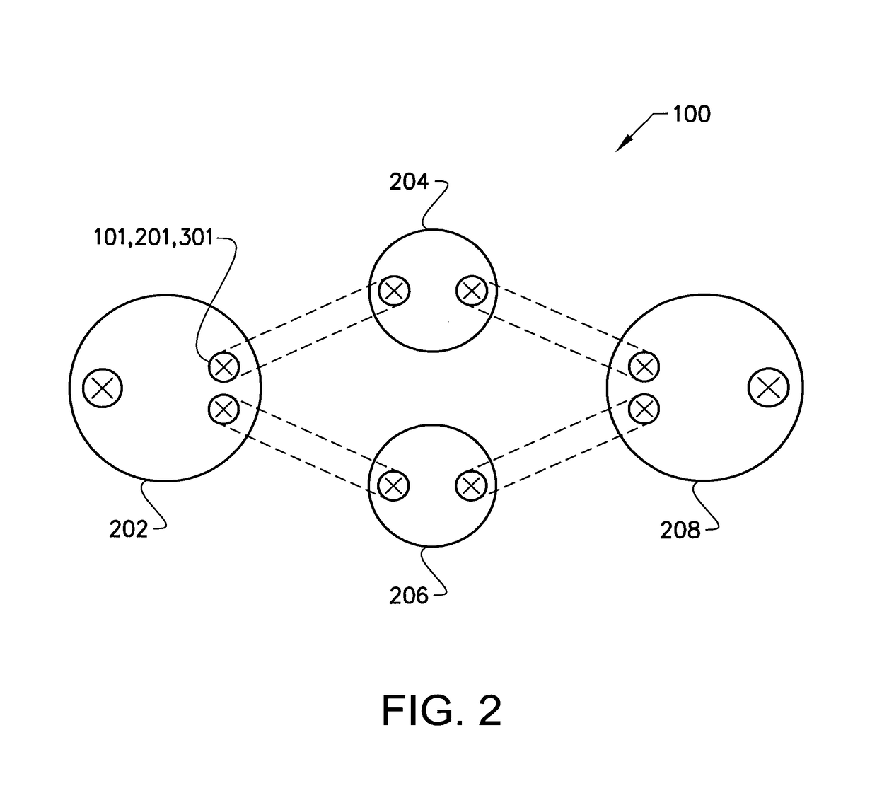
[0053]Turning to FIG. 2, illustrating an internal combustion engine arrangement 100 pro...


PUM


Abstract

A valve arrangement for a cylinder of an internal combustion engine arrangement includes a check valve configured to be positioned at an intake side port of the cylinder for controlling gas flow into the cylinder, wherein the valve arrangement further includes an intake valve arrangement positioned upstream from the check valve, and an actuating arrangement configured to controllably position the intake valve arrangement for closing the intake side port.

Description

BACKGROUND AND SUMMARY[0001]The present invention relates to a valve arrangement for a cylinder of an internal combustion engine arrangement. The invention is applicable for vehicles, in particularly heavy vehicles, such as e.g. trucks. However, although the invention will mainly be described in relation to a truck, the valve arrangement is of course also applicable for other type of vehicles, such as cars, industrial construction machines, wheel loaders, etc.[0002]For many years, the demand on internal combustion engines have been steadily increasing and engines are continuously developed to meet the various demands from the market. Reduction of exhaust gas, increasing engine efficiency, i.e. reduced fuel consumption, and lower noise level from the engines are some of the criteria that becomes an important aspect when choosing vehicle engine.[0003]In order to meet the described demands, various engine concepts have been developed throughout the years where conventional power cylind...

Claims


Application Information

Patent Timeline
Patent Type & Authority Patents(United States)
IPC IPC(8): F01L3/20F01L1/46F01L3/10F01L5/18F01L5/20F01L7/06F01L9/02F01L9/04F01L9/16F01L9/20
CPCF01L3/205F01L1/465F01L3/20F01L3/10F01L5/18F01L2820/034F01L7/06F01L9/026F01L9/04F01L2820/031F01L5/20F01L9/16F01L9/20
Inventor ANDERSSON, ARNEJIANG, BINCHENGLUNDGREN, STAFFANSANDSTROM, HAKAN
Owner VOLVO TRUCK CORP
Why Eureka
Try Eureka