Tamping machine for compacting the ballast bed of a track

a technology of ballast bed and track, which is applied in the direction of track superstructure, roads, constructions, etc., can solve the problems of increasing the fatigue limit of permanent bending stress, increasing the complexity of mechanical embodiments, and complex configuration of rotary apparatuses designed up until now, so as to increase the rotational range of the entire apparatus, increase the rigidity of the apparatus, and increase the stability of guided units

Active Publication Date: 2019-03-26
HP3 REAL GMBH
View PDF13 Cites 2 Cited by
  • Summary
  • Abstract
  • Description
  • Claims
  • Application Information

AI Technical Summary

Benefits of technology

[0004]The invention is thus based on the object of providing a transverse displacement device for units which allows independent displacement of both respective units of one machine side to such an extent that the main track and the diverging track of a switch can preferably be tamped in one single operation. The rigidity of the guidance of the units in the longitudinal direction of the track, in the vertical direction and furthermore the torsional stiffness shall be increased. According to an advantageous further development of the invention, an adjustment of the tamping units to the obliquely disposed longitudinal sleepers of a switch shall be possible.
[0009]Such tamping machines are used for setting and tamping a track. The tamping units of both machine sides can be displaced by a transverse displacement device beyond the machine frame to the outside. As a result, it is thus possible at a switch position to completely tamp both the main track and also the diverging track in one operation up to approximately the height of the cross frog. The transverse displacement device with the units that are transversely displaceable is further formed to be rotatable about the upright axis by a live ring. High stability of the guided units is achieved by the at least two sliding guides which are offset in height in relation to the track plane.
[0010]It is advantageous in this embodiment in accordance with the invention that greater transverse displacement paths can be achieved for the two units of one side by the transverse displacement apparatus. It is further advantageous that the inner unit of one side can be pushed out up to the boundary by the outer unit of the same side, which is why it is possible to process both the main track and also the diverging track in a switch in one operation. The formation of height-offset sliding guides advantageously leads to a higher stiffness of the apparatus for the protruding tamping units. The use of a live ring apparatus in accordance with the invention further increases the rotational range of the entire apparatus and offers lower need for maintenance and lower costs as a result of the simple configuration.

Problems solved by technology

The vertically limited flexural rigidity of the units thus guided in this manner leads to an oscillating behaviour during tamping as a result of the immersing forces, which leads to an increased permanent bending stress fatigue limit.
The rotary apparatuses designed up until now are complex in their configuration and require an increased amount of maintenance.
The limitation of the transverse displacement path of the inner unit of one side and the limited displacement paths in general prevent the tamping of a switch (main track and diverging track) in one operation.
Such embodiments are mechanically complex and lead to vibrations of the unit during immersion and tamping.

Method used


Image

  • Tamping machine for compacting the ballast bed of a track
  • Tamping machine for compacting the ballast bed of a track
  • Tamping machine for compacting the ballast bed of a track

Examples


Embodiment Construction

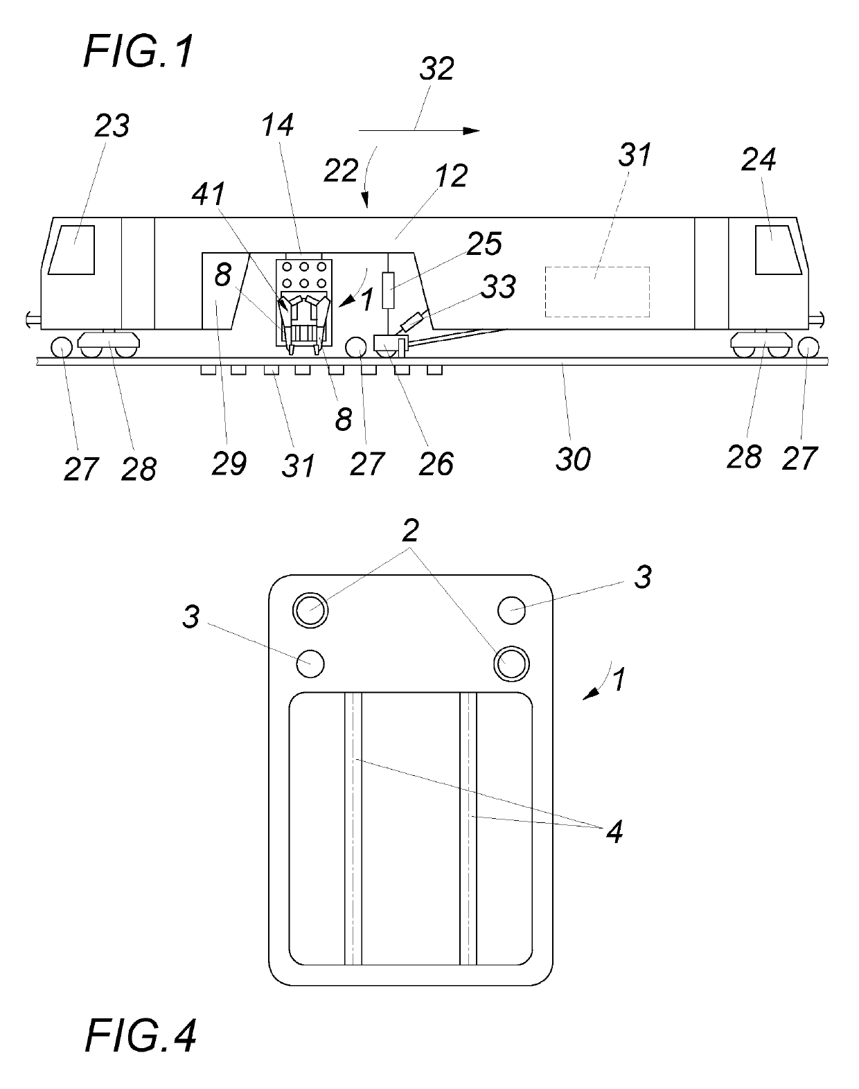
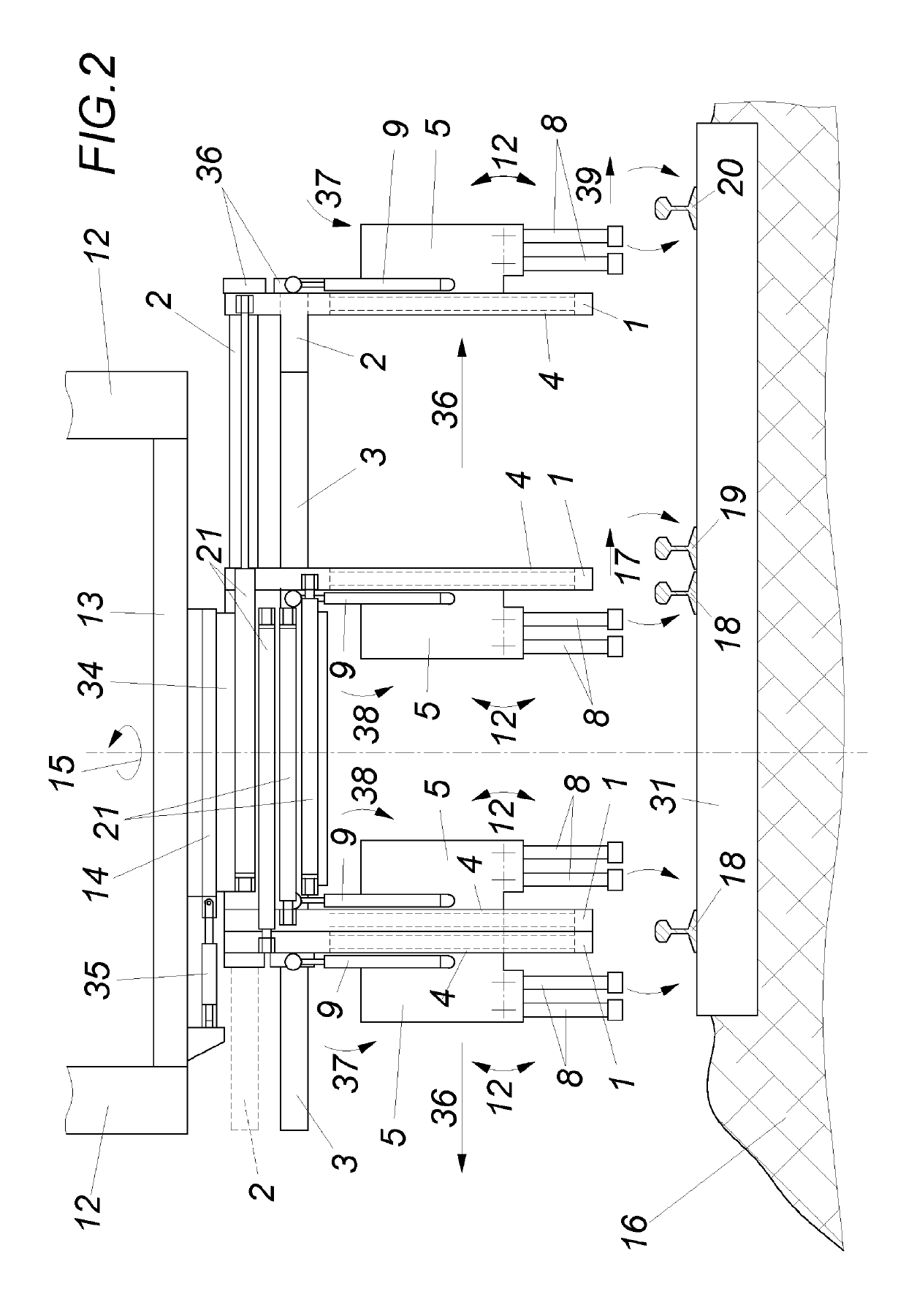
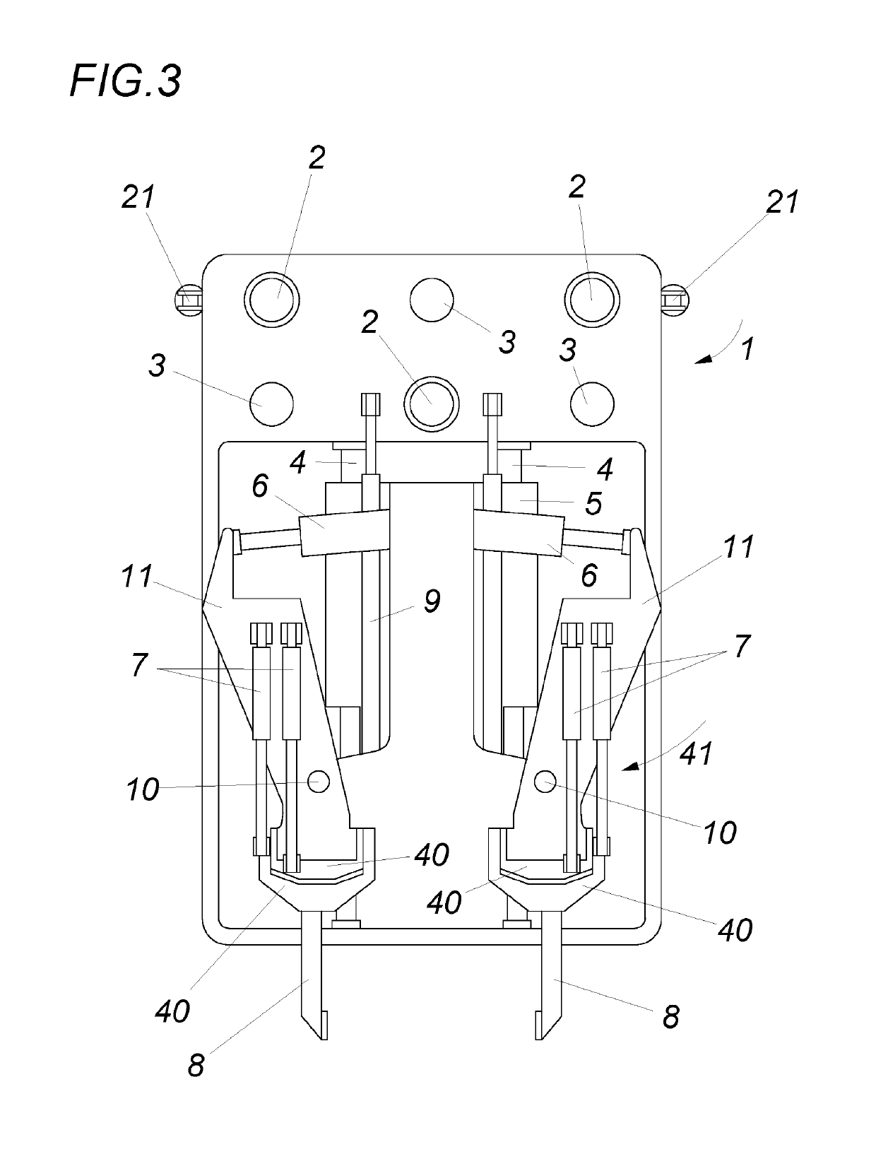
[0018]A tamping machine 22 (FIG. 1) with main supports 12 comprises tamping units 41 with a transverse displacement device 1, a lifting and lining unit 26 and a track lifting drive 25 as well as a track lining drive 33. Reference numeral 31 shows the conventional diesel engine which is used as a power source. 23 and 24 show the driver's cabins, 29 the operator's cabin. The machine 22 travels via the undercarriages 28 on the tracks 30, which are fastened on their part to the sleepers 31 to be tamped. The sleepers 31 are tamped by the tamping tines 8, which enter the ballast during the operation. The direction of work is indicated by reference numeral 32. The actual position of the track is recorded by the measuring carriage 27 and a measuring device, and the track is lifted, lined and fixed in this position by tamping by comparison with the track target position of the track. The tamping units are set up in their position in parallel to the longitudinal sleepers disposed obliquely in...


PUM


Abstract

A tamping machine for compacting the ballast bed of a track comprises at least two tamping units for each side of the tamping machine, which units can be displaced transversely relative to the longitudinal direction of the tamping machine by means of a transversal displacement device. At least two guides, in particular motion bars or sliding tubes are associated with both tamping units of each side of the tamping machine, said guides being offset in relation to one another with respect to their height and in the longitudinal direction of the tamping machine. Each outer tamping unit and its associated guides can be displaced transversely to the longitudinal direction of the tamping machine using an adjusting drive and the inner tamping unit can be displaced on the same guides, independently of the outer tamping unit, transversely to the longitudinal direction of the tamping machine using an adjusting drive.

Description

FIELD OF THE INVENTION[0001]The invention relates to a tamping machine for compacting the ballast bed of a track, comprising at least two respective tamping units for each side of the tamping machine for tamping the track, which units can each be displaced transversely relative to the longitudinal direction of the tamping machine by means of a transverse displacement device, and comprising a lifting and lining device for levelling and lining the track and optionally the diverging track of a switch, said lifting and lining device being arranged between on-track undercarriages in the working direction preferably before the tamping units.DESCRIPTION OF THE PRIOR ART[0002]Tamping machines are machines which correct the track position of switches and / or tracks. Measurement systems are used for this purpose which compare the actual position of the track height, the actual position of the track direction and the actual position of the superelevation of the track during the work and which c...

Claims


Application Information

Patent Timeline
Patent Type & Authority Patents(United States)
IPC IPC(8): E01B27/17
CPCE01B27/17E01B27/16E01B2203/12E01B2203/125
Inventor LICHTBERGER, BERNHARD
Owner HP3 REAL GMBH
Why Eureka
Try Eureka