Battery unit

a battery unit and battery case technology, applied in the direction of batteries, cell components, battery/fuel cell control arrangement, etc., can solve the problems of increasing mileage, and achieve the effect of sufficient rigidity of the battery case and efficient cooling of the battery

Active Publication Date: 2010-07-29
MITSUBISHI MOTORS CORP
View PDF1 Cites 16 Cited by
  • Summary
  • Abstract
  • Description
  • Claims
  • Application Information

AI Technical Summary

Benefits of technology

[0011]It is therefore an object of the present invention to provide a battery unit capable of maintaining sufficient rigidity of a battery case and also efficient cooling of a battery.
[0013]According to this structure, the rigidity of the battery case is maintained, and at the same time, the range of the battery module covered with the partitions can be reduced. Thus, the area of contact between the battery module and the cooling gas can be increased.
[0014]Consequently, it is possible to provide a battery unit capable of maintaining sufficient rigidity of a battery case and also efficient cooling of a battery.

Problems solved by technology

In particular, one great challenge for the electric vehicle is how to increase the mileage.

Method used


Image

  • Battery unit
  • Battery unit
  • Battery unit

Examples


Embodiment Construction

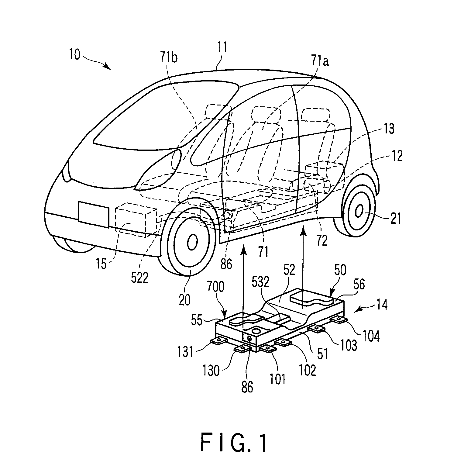
[0037]A battery unit according to one embodiment of the present invention is described with FIGS. 1 to 20. FIG. 1 shows one example of an electric vehicle 10. As shown in FIG. 1, the electric vehicle 10 comprises a motor 12 for driving and a charger 13 that are arranged in the rear part of a vehicle body 11, a battery unit 14 disposed under the floor of the vehicle body 11, etc. The battery unit 14 is located ahead of the motor 12. An air-conditioning heat exchanger unit 15 is disposed in the front part of the vehicle body 11. In addition, the motor 12 is not exclusively positioned in the rear part of the vehicle body 11. For example, the motor 12 may be disposed in the front part of the vehicle body 11.

[0038]A front wheel 20 of the electric vehicle 10 is supported on the vehicle body 11 by an unshown front suspension. A rear wheel 21 is supported on the vehicle body 11 by an unshown rear suspension.

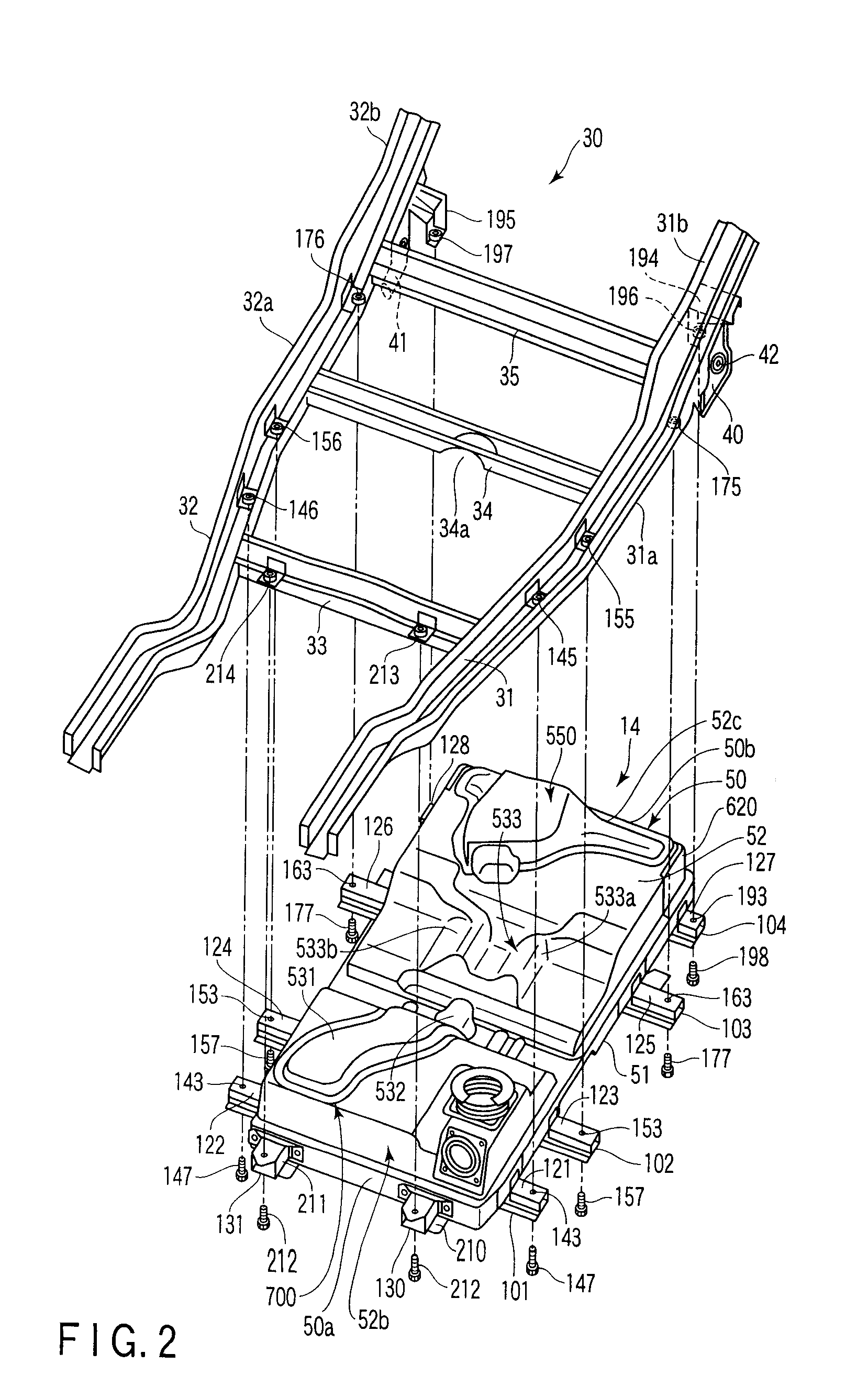
[0039]FIG. 2 shows the battery unit 14 separated from a frame body structure 30 whic...


PUM

PropertyMeasurementUnit
widthaaaaaaaaaa
heightaaaaaaaaaa
structureaaaaaaaaaa

Abstract

A battery unit comprises a battery case, and a plurality of battery modules stored and held in the battery case. The battery case includes a bottom wall and a partition. The plurality of battery modules are mounted on the bottom wall. The partition is provided and erected on the bottom wall. The partition separates the battery modules adjacent in a second direction traversing a first direction. The first direction is oriented from a first end of the battery case at which an inlet is formed to a second end at which an outlet is formed. The partition extends along a plane where the battery modules face each other in the second direction along the battery modules. The partition is inclined in the extending direction.

Description

CROSS REFERENCE TO RELATED APPLICATIONS[0001]This application is a Divisional of co-pending application Ser. No. 12 / 411,959 filed on Mar. 26, 2009 and for which priority is claimed under 35 U.S.C. §120. Application No. JP2007-256208 is the national phase of PCT International Application No. PCT / JP2008 / 054806 filed on Mar. 14, 2008 under 35 U.S.C. §371. The entire contents of each of the above-identified applications are hereby incorporated by reference.BACKGROUND OF THE INVENTION[0002]1. Field of the Invention[0003]The present invention relates to a battery unit used as a power supply for, for example, an electric vehicle.[0004]2. Description of the Related Art[0005]An electric vehicle is equipped with a battery unit as a power supply for running. The battery unit comprises a battery module, a battery case for storing the battery module, etc. The battery case of the battery unit of this type includes a battery carrier for storing a battery, and a battery carrier cover for covering t...

Claims


Application Information

Patent Timeline
Patent Type & Authority Applications(United States)
IPC IPC(8): H01M10/50H01M50/529B60K1/04B60K11/06B60L11/18H01M10/60H01M10/613H01M10/617H01M10/625H01M10/647H01M10/6556H01M10/6563H01M10/6566H01M10/663H01M50/204H01M50/291H01M50/528
CPCB60K1/04B60K2001/005B60K2001/0438B60L11/1864B60L11/1874Y02T10/7061B60L11/1879H01M2/0247H01M2/1083H01M2220/20Y02T10/7005B60L11/1877B60L58/21B60L58/26B60L50/66B60L50/64Y02T10/70Y02E60/10H01M50/26H01M50/204H01M50/291
Inventor NISHINO, HARUCHIKAIBUKI, TAKESHITAKASAKI, SEIICHI
Owner MITSUBISHI MOTORS CORP
Why Eureka
Try Eureka