Brake shoe

a technology of brake shoes and joints, applied in the direction of mechanically actuated drum brakes, mechanical apparatus, coatings, etc., can solve the problems of inaccuracy quickly arising during the joining, and achieve the effect of less outlay for coordination during the mounting

Active Publication Date: 2019-04-09
SAF HOLLAND GMBH
View PDF23 Cites 0 Cited by
  • Summary
  • Abstract
  • Description
  • Claims
  • Application Information

AI Technical Summary

Benefits of technology

[0004]According to the invention, a brake shoe, in particular of a drum brake for utility vehicles, comprises a lining plate and a bridge unit, the bridge unit being formed as a one-piece body having at least two bridge plates. Typically, the drum brake comprises a brake drum, against which two movably mounted brake shoes, for example on a brake carrier or a brake anchor plate, are pressed from the inside by an appropriate device. The mounting of the brake shoe and the introduction of force take place via the bridge plates, which advantageously impart the necessary stiffness to the entire arrangement. Pressing on the brake shoes can be carried out directly mechanically via a camshaft, an expanding wedge or a wheel brake cylinder. In order to provide the actual braking action, an appropriate brake lining is arranged on the lining plate of the brake shoe, in particular riveted, for example. In the prior art, two mutually independent flanges or else webs are welded onto the rear side of the lining plate. These have to be positioned exactly relative to the lining plate and to each other since, as already mentioned, the mounting of the brake shoe and the introduction of force take place via the webs or bridge plates. Advantageously, the brake shoe now has the bridge unit, which is formed as a one-part or one-piece body comprising the at least two bridge plates. This configuration makes it possible to dispense with tolerances which would arise as a result of the assembly of the individual components. Since the bridge unit consists of one piece, the coordination during the mounting requires less outlay. Fabrication and mounting steps can therefore be dispensed with as compared with the prior art. The bridge unit can be fixed as a unit to the rear side of the lining plate with a form fit and / or force fit and / or an integral connection. It is preferably welded, for example. Advantageously, the bridge unit is formed from a homogeneous material.
[0007]According to one embodiment, the connecting plate has at least one opening or a recess or forms the same. This likewise permits a further reduction in weight and can in addition be used for dissipation of heat from the bridge unit formed in one piece. The opening can be formed as a hole, in particular as a round or circular hole. However, also preferred is an elongated opening, which extends along the circumferential direction, at least in some sections. The width of the opening is dimensioned in such a way that parts of the connecting web still remain. This permits a high stiffness and low use of material, especially in the longitudinal direction / circumferential direction. According to one embodiment, a ratio of a width of the connecting plate to a width of the opening lies in a range from about 0.1-0.9, preferably around 0.2-0.8. The connecting plate in general advantageously permits an increase in the stiffness of the bridge unit and improved dissipation of heat and also heat distribution. Thus, heat differences and temperature peaks from one bridge plate to the other can easily be compensated for via the connecting plate. Via the arrangements of openings / recesses in the connecting plate or connecting plates or possibly also in the bridge plates themselves, the temperature distribution can be adapted individually. Particularly expediently, by means of two openings (for example round opening and slot) located adjacent to each other in the connecting plate, a web area is formed which forms an engagement area for a return spring to be hooked in.

Problems solved by technology

In addition, on account of the relatively high number of components, inaccuracies quickly arise during the joining, in particular as a consequence of the accumulating tolerances.

Method used


Image

  • Brake shoe
  • Brake shoe
  • Brake shoe

Examples


Embodiment Construction

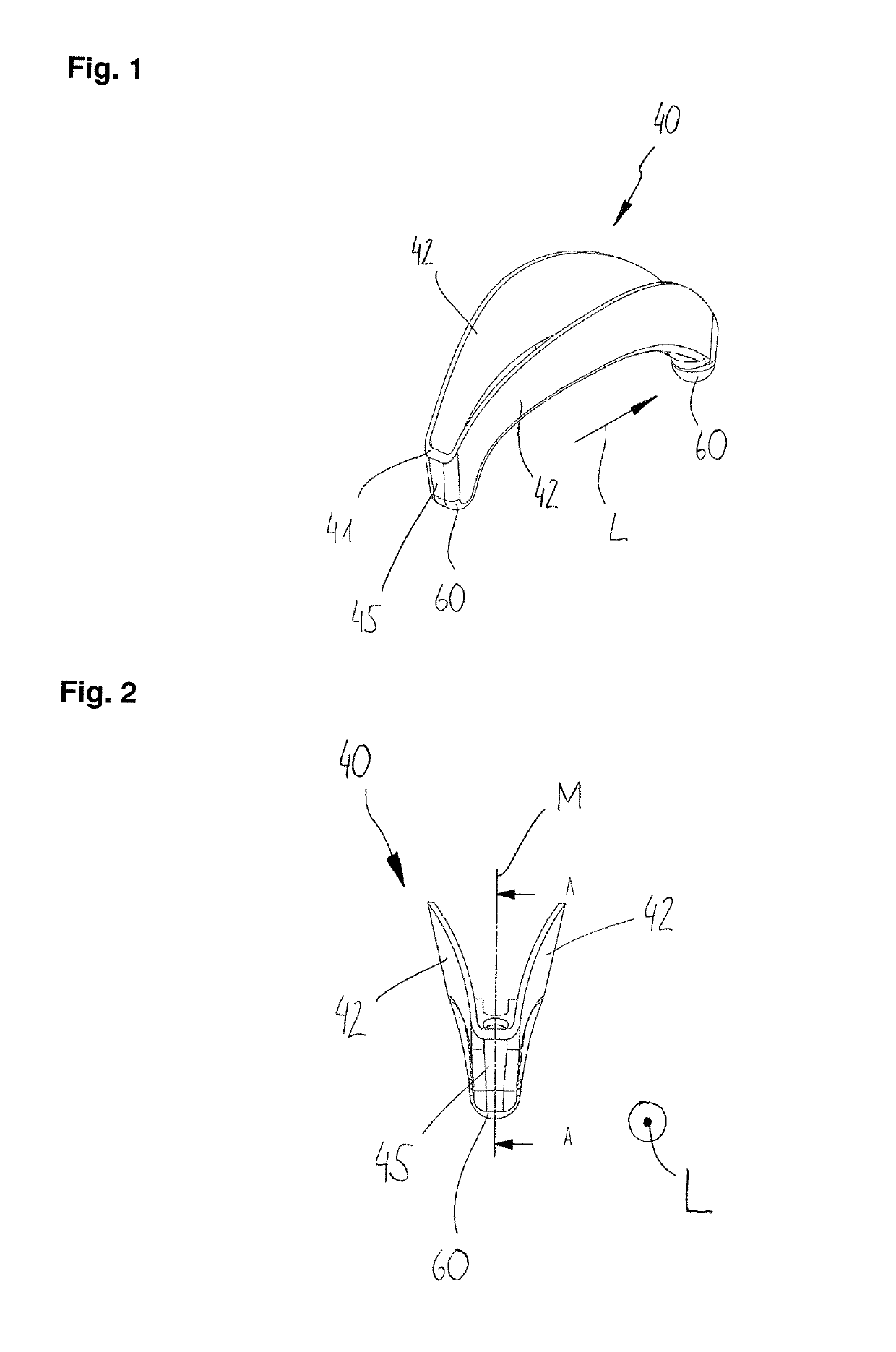
[0028]FIG. 1 shows in a perspective illustration a bridge unit 40 comprising two bridge plates 42, which are connected via transverse plates 45. The bridge unit 40 extends along a longitudinal direction L (or along a circumferential direction of the brake drum) and, at its respective ends, respectively forms functional areas 60, the (rear) one being formed spherically, in particular in the shape of a ball, the front one more likely cylindrically. It is possible to see clearly the one-piece configuration on the bridge unit 40, comprising the two bridge plates 42, the transverse plates 45 and the functional areas 60. The bridge unit 40 forms a circumferential arrangement surface 41, via which the arrangement and fixing on a brake lining, not illustrated here, is carried out, for example via a welded connection. Here, the great advantage of the bridge unit 40 becomes clear, specifically that only one component has to be “handled”. In addition, the decreasing height of the bridge plates...


PUM

PropertyMeasurementUnit
thicknessaaaaaaaaaa
thicknessaaaaaaaaaa
angleaaaaaaaaaa

Abstract

Brake shoe, in particular of a drum brake for utility vehicles, includes a lining plate and a bridge unit, wherein the bridge unit is formed as a one-piece body comprising at least two bridge plates.

Description

BACKGROUND OF THE INVENTION[0001]The present invention relates to a brake shoe, in particular a drum brake for utility vehicles, a bridge unit for a brake shoe and a drum brake.[0002]Drum brakes are still the preferred brake type in the utility vehicle segment and for trailers. Here, the basic structure comprises a rotating brake drum, against which two movably mounted brake shoes are pressed from the inside by an appropriate device, which produces the braking force. Known brake shoes normally comprise a number of parts which, for example, are joined together by welding and pressing: the lining plate, two webs, which are fixed to the lining plate at the rear, and corresponding mounting points or mounting shells which are used to mount the brake shoe. The outlay on fabrication and handling during the production of the brake shoes is correspondingly high. In addition, on account of the relatively high number of components, inaccuracies quickly arise during the joining, in particular a...

Claims


Application Information

Patent Timeline
Patent Type & Authority Patents(United States)
IPC IPC(8): F16D65/08F16D65/22F16D51/28F16D51/22F16D65/02F16D125/30
CPCF16D65/08F16D51/22F16D51/28F16D65/22F16D2250/0076F16D2065/1344F16D2125/30F16D2250/0046F16D2065/132
Inventor ARPACI, MUHAMMET
Owner SAF HOLLAND GMBH
Why Eureka
Try Eureka