Exhaust gas heat exchanger with an oscillationattenuated bundle of exchanger tubes

a heat exchanger and bundle technology, applied in indirect heat exchangers, machines/engines, lighting and heating apparatus, etc., can solve the problems that the surface of a metallic cast part cannot be designed as inert comparable with a stainless steel surface, and it is difficult if not impossible to achieve the design of inert surfaces of metallic cast parts. , the vibration capability of the bundle of exchanger tubes can be further reduced, and the vibration capacity is strong reduced

Active Publication Date: 2013-03-05
HANON SYST
View PDF20 Cites 8 Cited by
  • Summary
  • Abstract
  • Description
  • Claims
  • Application Information

AI Technical Summary

Benefits of technology

[0011]A heat exchanger of the invention is provided for the exhaust train of a motor vehicle. The heat exchanger comprises a bundle of separately formed exhaust carrying exchanger tubes that are connected in parallel in terms of fluid flow. The exchanger tubes are disposed in a separately formed, closed housing through which a coolant flows. The coolant flows around the exchanger tubes outside thereof. In accordance with the invention, there is provided a bandage for the bundle of heat exchanger tubes which is disposed on the bundle outside thereof. The bandage further connects a plurality of heat exchanger tubes together for a solid mechanical connection to militate against a vibration of at least the outer tubes of the bundle.
[0012]In a further developed implementation, the bandage further forms a mechanical abutment for the heat exchanger tubes joined together by the bandage with respect to the housing. In this way, the bandage not only prevents relative vibrations of the exchanger tubes of the bundle with respect to each other but also collective vibrations of the bundle in general with respect to the housing surrounding the bundle.
[0016]The particular, vibration-reduced implementation of the heat exchanger bundle of the invention is of particular advantage if the inlets and the outlets of the exchanger tubes are disposed outside of the heat exchanger housing and if a winding flow path extends in the exchanger tubes within the housing, the flow path including an angle of rotation of at least 135°, preferably however of 180°. In such a u-shaped or semi-circular configuration of the exchanger tubes, the exchanger tubes typically only abut mechanically at the points at which they are connected through the wall of the heat exchanger housing, thus forming a system very well capable of vibrating. This capability of vibration is strongly reduced by the bandage that is provided in accordance with the invention and forms a surrounding grip around the bundle of tubes. It is even further reduced by the baffle already mentioned herein above, which is also connected to a plurality of exchanger tubes.
[0017]The vibrating capability of the bundle of exchanger tubes can be further reduced if a stiffening element mechanically solidly connecting a plurality of heat exchanger tubes is disposed inside the bundle. Such a stiffening element can be made from a suitably shaped metal strip for example, which is connected to the exchanger tubes by means of soldering or welding. The metal strip can be equipped with the necessary stiffness by giving the metal strip the appropriate profile, for example a V or a U profile.
[0018]Preferably, the exchanger tubes in the heat exchanger of the invention are made from one piece, at least between the points at which they are conducted through the wall of the heat exchanger housing, and are made from a corrosion and heat resistant material such as stainless steel, aluminium or an aluminium alloy. In order to achieve best possible heat transfer from the hot combustion exhaust carried in the exchanger tubes and the coolant flowing around the exchanger tubes outside thereof, the exchanger tubes are equipped with the least possible wall thickness, their vibration capability increasing as a result thereof, though. The thermal efficiency can be further increased if intensive turbulence is ensured in the exhaust gas carried in the exchanger tubes; for this purpose, a spiral structure can be formed on the inner surfaces of the exchanger tubes. In a particularly efficient way, such a spiral structure can be produced by stamping the wall of the respective exchanger tubes; as a result, the stiffness of the exchanger tubes is even further reduced, this causing the vibration capability of the bundle of exchanger tubes to increase even further. In particular in this context, the previously mentioned vibration-reduced measures taken at the bundle of exchanger tubes are advantageous.

Problems solved by technology

Since the efficiency of an internal combustion engine is typically dependent on the temperature of the combustion air fed into the combustion chamber of the internal combustion engine, the combustion gases cannot be recirculated to the intake side immediately after having left the combustion chamber of the internal combustion engine.
Since the very hot combustion gases are reactive due to the fact that the fuel never burns completely, the problem here is that it is technically difficult if not impossible to design the surfaces of a metallic cast part as inert surfaces comparable with a stainless steel surface.

Method used


Image

  • Exhaust gas heat exchanger with an oscillationattenuated bundle of exchanger tubes
  • Exhaust gas heat exchanger with an oscillationattenuated bundle of exchanger tubes
  • Exhaust gas heat exchanger with an oscillationattenuated bundle of exchanger tubes

Examples


Embodiment Construction

[0044]The following detailed description and appended drawings describe and illustrate various embodiments of the invention. The description and drawings serve to enable one skilled in the art to make and use the invention, and are not intended to limit the scope of the invention in any manner. In respect of the methods disclosed, the steps presented are exemplary in nature, and thus, the order of the steps is not necessary or critical.

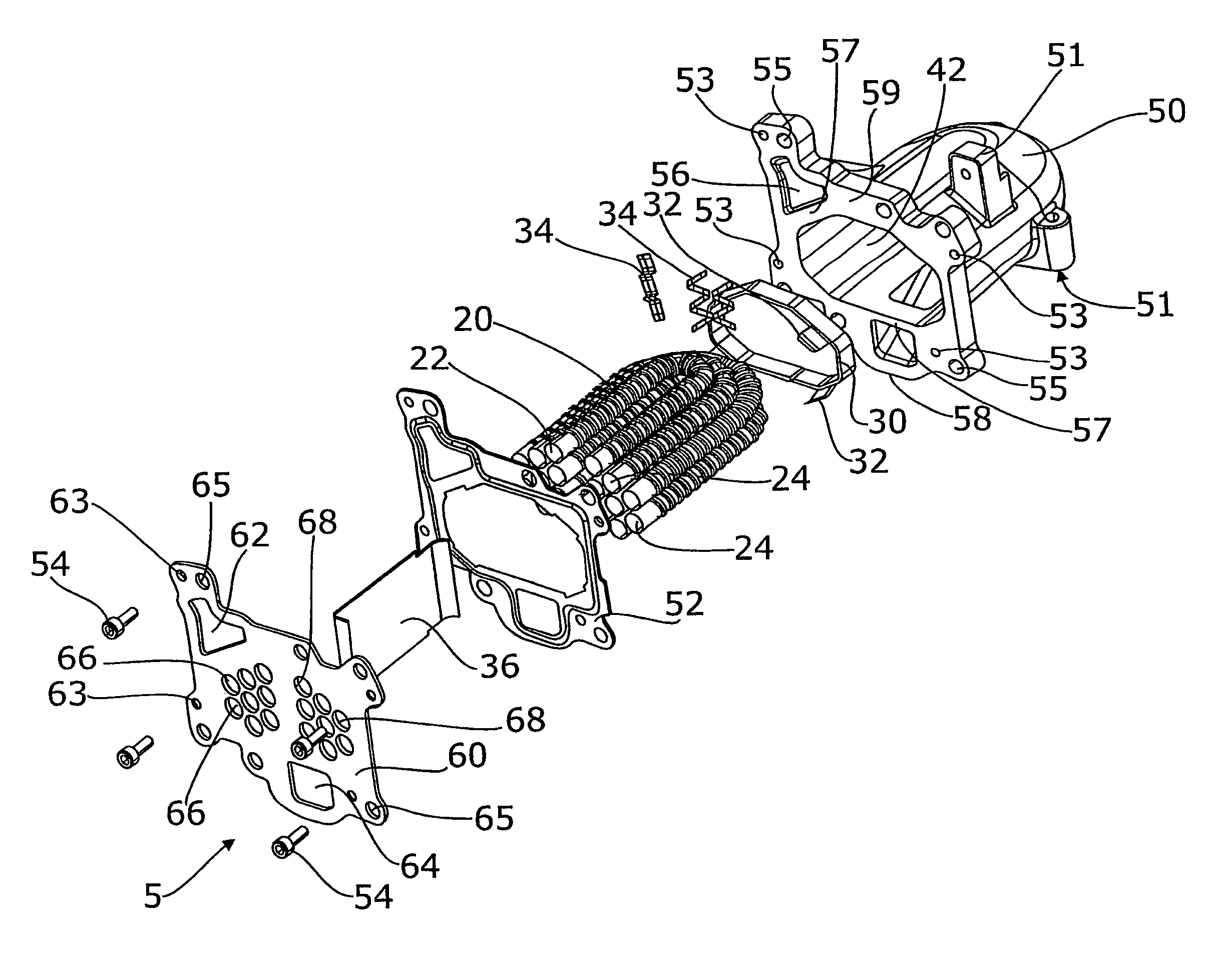
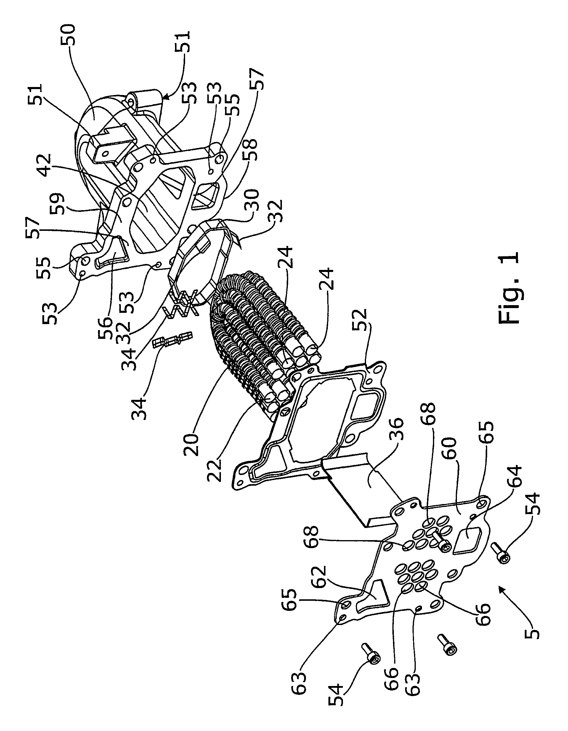
[0045]FIG. 1 shows an exploded view of an exhaust gas heat exchanger 1 of the invention according to a first exemplary embodiment. The heat exchanger 1 includes a housing 40 consisting of a housing case 50 closed by means of a housing cover 60. The housing case 50 is configured to be a cast part and may be made from aluminium die casting in particular. Alternatively, the housing case 50 in the exemplary embodiment shown may be made from any material that can be processed by casting on the one side and that has sufficient thermal stability on the other...


PUM


Abstract

A heat exchanger is disclosed for the exhaust gas train of a motor vehicle. The heat exchanger includes a bundle of separately formed exhaust gas carrying exchanger tubes that is disposed in a closed housing formed separately, a coolant flowing through the housing and around the outside of the exchanger tubes. A bandage is disposed on the bundle of exchanger tubes mechanically connecting a plurality of the exchanger tubes to militate against an oscillation of the exchanger tubes.

Description

CROSS-REFERENCE TO RELATED APPLICATION[0001]This application claims the benefit of German provisional patent application serial no. DE 102007032188.2 filed Jul. 11, 2007, and German non-provisional patent application serial no. DE 102008002430.9 filed Jun. 13, 2008, each of which is hereby incorporated herein by reference in its entirety.FIELD OF THE INVENTION[0002]The present invention relates to a heat exchanger for an exhaust train of a motor vehicle, and more specifically to an exhaust gas recirculation system for an internal combustion engine of a motor vehicle.BACKGROUND OF THE INVENTION[0003]Due to the ever more stringent legal regulations regarding exhaust emission of motor vehicles, in particular regarding emission of nitrogen oxides, recirculation of combustion exhaust to the inlet side of the internal combustion engine is state of the art in the field of internal combustion engines. The combustion gases themselves do not participate again in the combustion process in the ...

Claims


Application Information

Patent Timeline
Patent Type & Authority Patents(United States)
IPC IPC(8): F28F9/007
CPCF02M25/0714F02M25/0737F28D7/06F28F1/06F28F9/0132F02B29/0462F28D1/0475F28F1/08F01N2240/02F28F2225/04Y02T10/121F28F2009/224F02M26/11F02M26/32
Inventor CAPELLE, ANDREASHEBERT, GUILLAUMEREPA, ANDREJ
Owner HANON SYST
Why Eureka
Try Eureka