Tool for grinding toothed workpieces having collision contours

a technology of collision contours and workpieces, which is applied in the direction of gear teeth, gear teeth, gear-teeth manufacturing apparatus, etc., can solve the problems of inability to use grinding tools according to prior art dimensions, inability to use economicalally, and inability to dressable abrasive coating to such an exten

Active Publication Date: 2017-08-01
LIEBHERR VERZAHNTECHNIK GMBH
View PDF13 Cites 3 Cited by
  • Summary
  • Abstract
  • Description
  • Claims
  • Application Information

AI Technical Summary

Benefits of technology

[0023]A combination is also conceivable, made of a dressable grinding tool to machine a collision contour together with a non-dressable tool. In this way, a still smaller collision contour can be mach...

Problems solved by technology

A use of grinding tools with dimensions according to the prior art is no longer possible for tooth systems of this type due to reasons of collisions.
If a tool with a reduced outer diame...

Method used


Image

  • Tool for grinding toothed workpieces having collision contours
  • Tool for grinding toothed workpieces having collision contours
  • Tool for grinding toothed workpieces having collision contours

Examples


Embodiment Construction

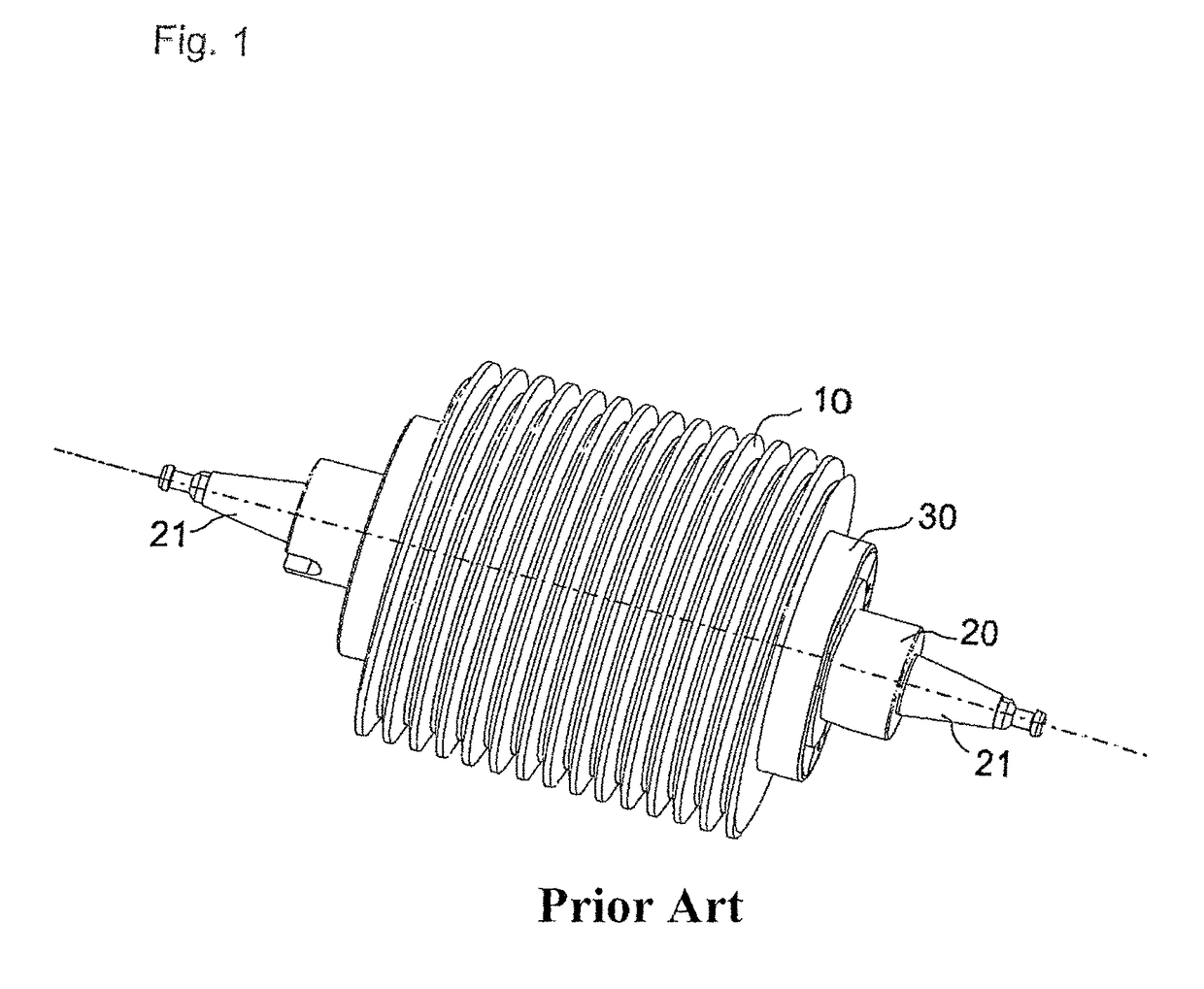
[0030]FIG. 1 shows a grinding tool according to the prior art. One or more grinding tools 10 are mounted on a tool mandrel 20 having an outer surface defining an outer tool mandrel diameter as well as double-sided mounting surfaces 21 for mounting the tool in the machine head of a tooth grinding machine (not depicted here), and each tool is fixed on the tool mandrel by fixing with a clamping cover or clamping unit 30.

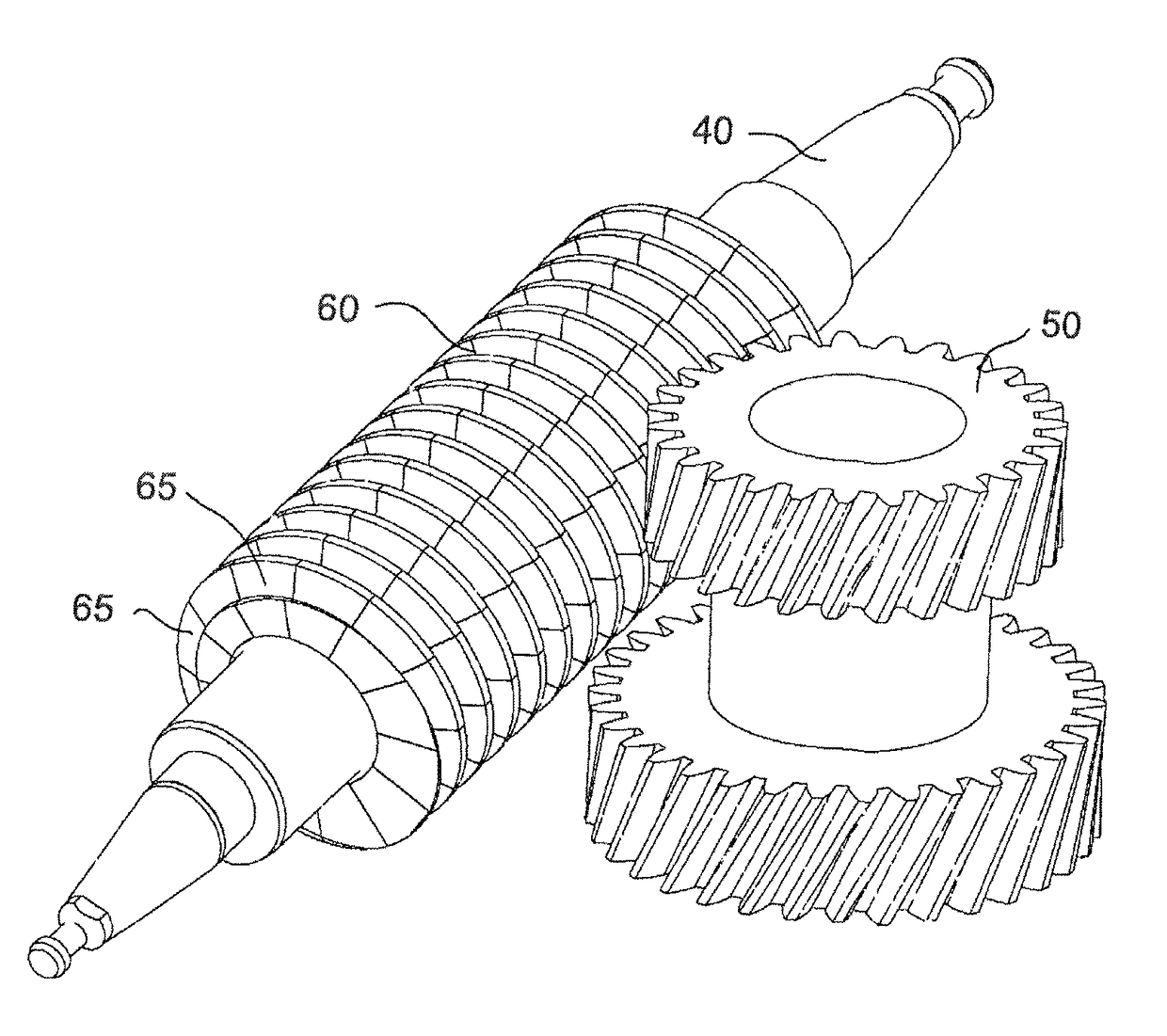
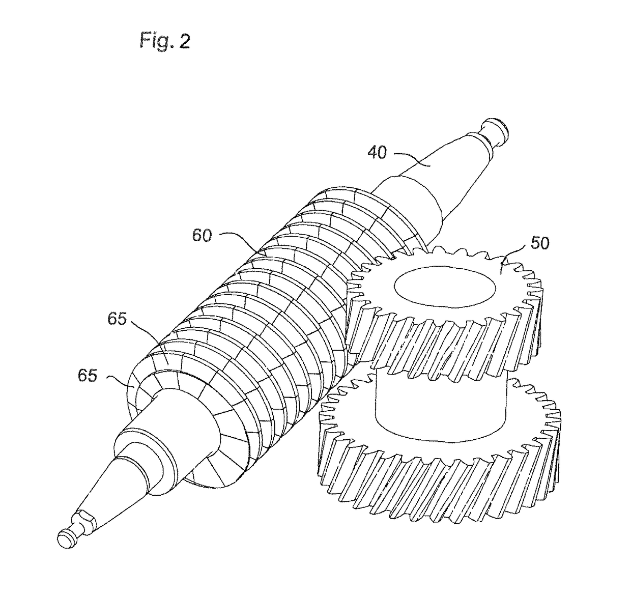
[0031]FIG. 2 shows a perspective view of a grinding tool 60 according to the invention. By means of the double toothing 50 depicted, the difficulty can also be seen which leads to a limit of the diameter of the grinding tool. Based on the helical gearing and the slanted position of the grinding tool necessitated thereby in the engaged position, the tool diameter may not exceed a certain diameter, since otherwise this would lead to a collision of the tool with the lower toothing.

[0032]The design of the worm grinding wheel can likewise be seen, which design consists of a ...


PUM

PropertyMeasurementUnit
Diameteraaaaaaaaaa

Abstract

A tool for generating tooth systems by grinding when the maximum tool diameter is limited by collision contours on the workpiece has a dressable grinding tool that is tightly connected to the tool holder. In one preferred arrangement, the dressable grinding tool is glued on the tool holder.

Description

BACKGROUND OF THE INVENTION[0001]This invention relates to a tool for grinding toothed workpieces using dressable grinding tools that are optimized with regard to the maximum tool diameter by collision surfaces, like interference contours or limitations from preprocessing, such as tool run-out.[0002]Known tools for generating grinding of tooth systems always have a tool holding mandrel or flange by means of which the tool is held in the grinding machine. This mandrel / flange requires a certain minimum diameter in order to have the necessary stability. The tool(s) is(are) fitted on this mandrel / flange and generally fastened to the mandrel / flange by laterally arranged fastening elements. So that a collision between the tool and holding mandrel / flange does not occur during grinding, the usable tool diameter only begins after this region. A certain minimum tool diameter results due to this design principle and due to the coating thickness necessary in the abrasive coating for an economic...

Claims


Application Information

Patent Timeline
IPC IPC(8): B23F21/00B23F21/02B23F5/04B24B53/075B24D11/04B24B53/085B24D5/12B24D5/14B24D18/00B24D5/06
CPCB23F21/005B23F5/04B23F21/026B24B53/075B24B53/085B24D5/066B24D5/123B24D5/14B24D11/04B24D18/0072
Inventor BREITH, THOMASZANKL, MANFRED
Owner LIEBHERR VERZAHNTECHNIK GMBH
Why Eureka
Try Eureka