Single plate hydrodynamic bearing cartridge

a technology of hydrodynamic bearings and cartridges, applied in the direction of bearings, shafts and bearings, rotary bearings, etc., can solve the problems of prone to several shortcomings of the conventional bearing system described above, physical contact between raceways and balls, and vibration generated, etc., to achieve reliable, repeatable design, and simple design. , the effect of high adaptability and scalable us

Inactive Publication Date: 2005-05-12
SEAGATE TECH LLC
View PDF2 Cites 10 Cited by
  • Summary
  • Abstract
  • Description
  • Claims
  • Application Information

AI Technical Summary

Benefits of technology

[0010] It is therefore a primary objective of the present invention to provide a hydrodynamic bearing which is simple in design, and highly adaptable and scalable for use in many different environments. It is a further objective of the invention to provide a hydrodynamic bearing having a reliable, repeatable design so that the bearing has the necessary stiffness to be used in applications which have no tolerance for tilt, wobble, or other inaccuracies.
[0011] It is a further and related objective of the present invention to provide a hydrodynamic bearing in which the fluid circulation is controlled and directed so that the wear and tear on the two prior surfaces defining the bearing is minimized.
[0012] Another related objective of the present invention is to provide for fluid circulation within the hydrodynamic bearing such that the possibility of voids within the lubricant is minimized.
[0013] A related objective of the invention is to provide a hydrodynamic bearing design having optimized boundary conditions between the various sections of the bearings to optimize fluid flow and diminish sensitivity to temperature and machining tolerances, thereby providing a greater consistency in the dynamic performance of the invention.
[0014] These and other objectives are achieved by providing a hydrodynamic bearing having a shaft relatively rotatable with respect to a surrounding sleeve and having a thrust plate on one end thereof rotating in a recess of the sleeve. The shaft is preferably interrupted by a equi-pressure groove accessing a central reservoir in the shaft and having journal bearings defined by herringbone patterns above and below the groove to stabilize and provide stiffness to the cartridge. The stiffness of the cartridge is further enhanced by a thrust plate carried at one end of the shaft and rotating in a recess of the sleeve and being used to define thrust bearings on either surface thereof. In a typical embodiment, chevron patterns may be coined or etched on both surfaces of the thrust plate so that appropriate pressure patterns can be set up between the thrust plate surface and either a shoulder of the sleeve or a facing counterplate. Alternatively, a counterplate may be provided in which the chevron pattern is stamped thereon, and may in a preferred embodiment even extend beyond the edges of the thrust plate and the recess in which it rotates so that disturbances to the pressure patterns are minimized.

Problems solved by technology

The conventional bearing system described above is prone, however, to several shortcomings.
First is the problem of vibration generated by the balls rolling on the raceways.
Ball bearings in such cartridges frequently run under conditions that result in physical contact between raceways and balls; this occurs in spite of the lubrication layer provided by the bearing oil or grease.
This vibration results in misalignment between whatever device is supported for rotation and the surrounding environment.
This source of vibration limits therefore the accuracy and the overall performance of the system incorporating the cartridge.
Another problem is related to damage caused by shocks and rough handling.
Since the contact surfaces in ball bearings are very small, the resulting contact pressures may exceed the yield strength of the bearing material and leave permanent deformation and damage on raceways and balls, which would also result in tilt, wobble, or unbalanced operation of the bearing.
Moreover, mechanical bearings are not always scalable to smaller dimensions.
This is a significant drawback since the tendency in the high technology industry has been to continually shrink the physical dimensions.
However, it is apparent that a difficulty with such a hydrodynamic bearing design is their sensitivity both to machining tolerances and the temperature ranges across which they are utilized.
In other words, it is important to have a very stiff bearing which does not allow for any tilting of the rotating part relative to the stationary part.
A further difficulty with prior art designs is that frequently voids or gas bubbles occur in the bearing area, thereby reducing the effective bearing surface and the related load capacity.

Method used


Image

  • Single plate hydrodynamic bearing cartridge
  • Single plate hydrodynamic bearing cartridge
  • Single plate hydrodynamic bearing cartridge

Examples


Embodiment Construction

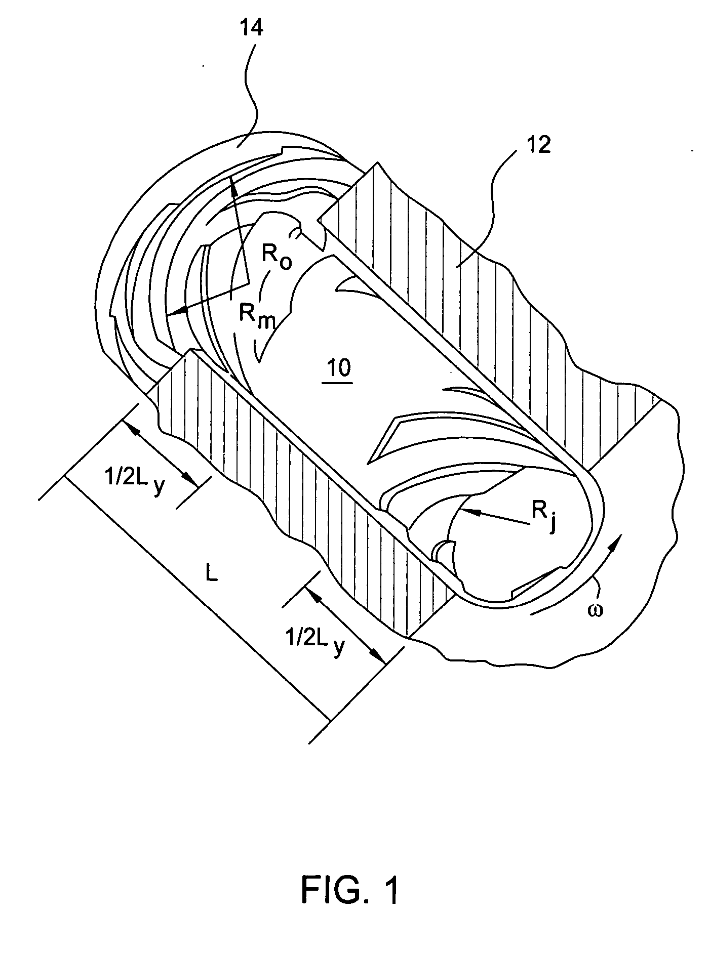
[0020] The basic principles of the present invention are derived from hydrodynamic bearings as already known in the technology, an example of which is shown in FIG. 1. As shown in this figure, a journal bearing includes a shaft 10 which is rotating relative to a bushing or a sleeve 12, with one of the opposing two surfaces (in this case the shaft closed) carrying cylindrical sections of spiral grooves. A thrust plate 14 may also be provided at or near one end of the shaft 10 carrying concentric spiral groove sections either on the plate itself or on the sleeve surface that it faces. Relative rotation of the shaft churns and pumps the fluid as a function of the direction, width, and angle of the grooves with respect to the sense of rotation. The pumping action builds up multiple pressure zones along the journal and the thrust plates, maintaining a fluid film between the rotating parts and providing the desired stiffness for the bearing.

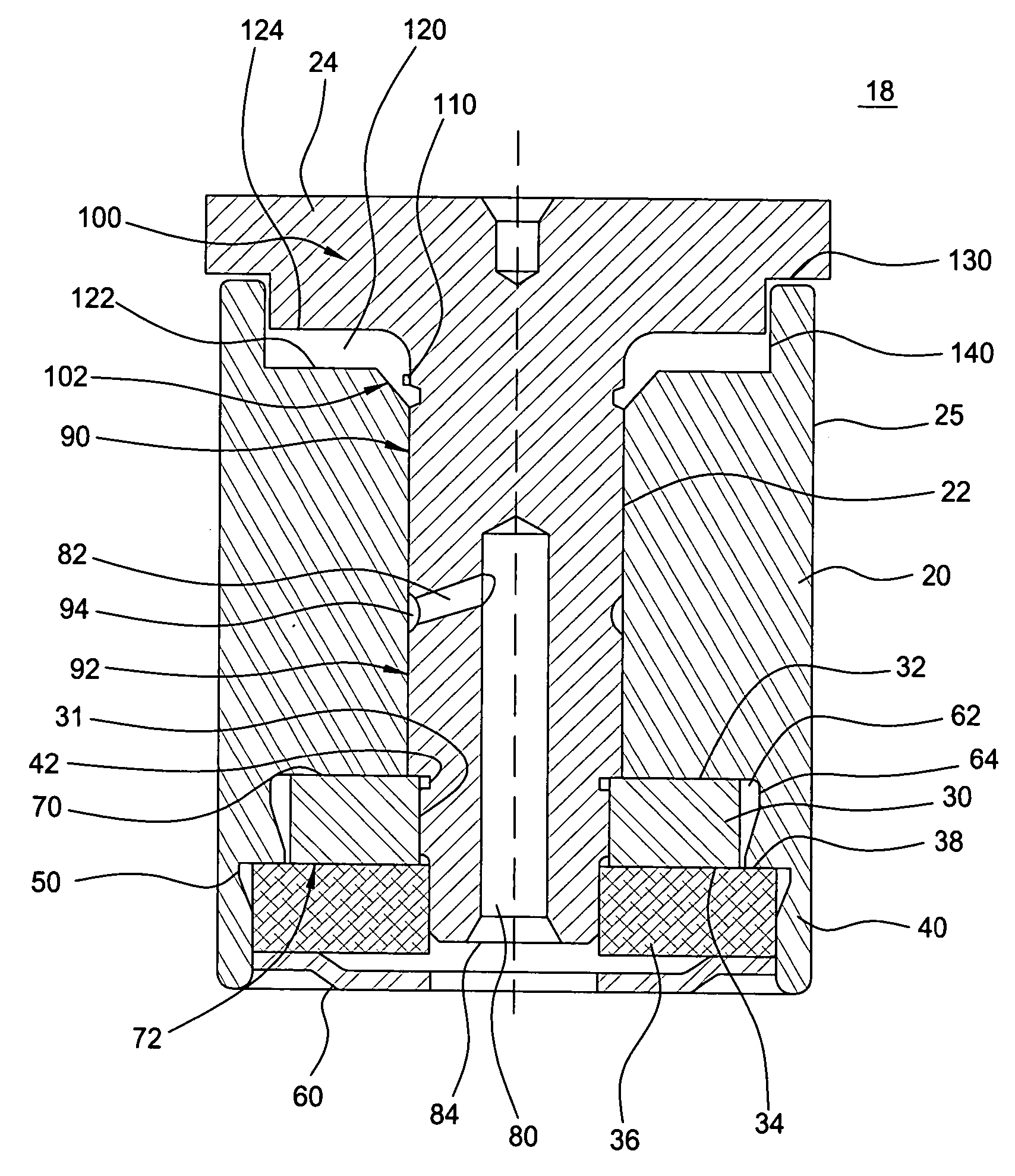
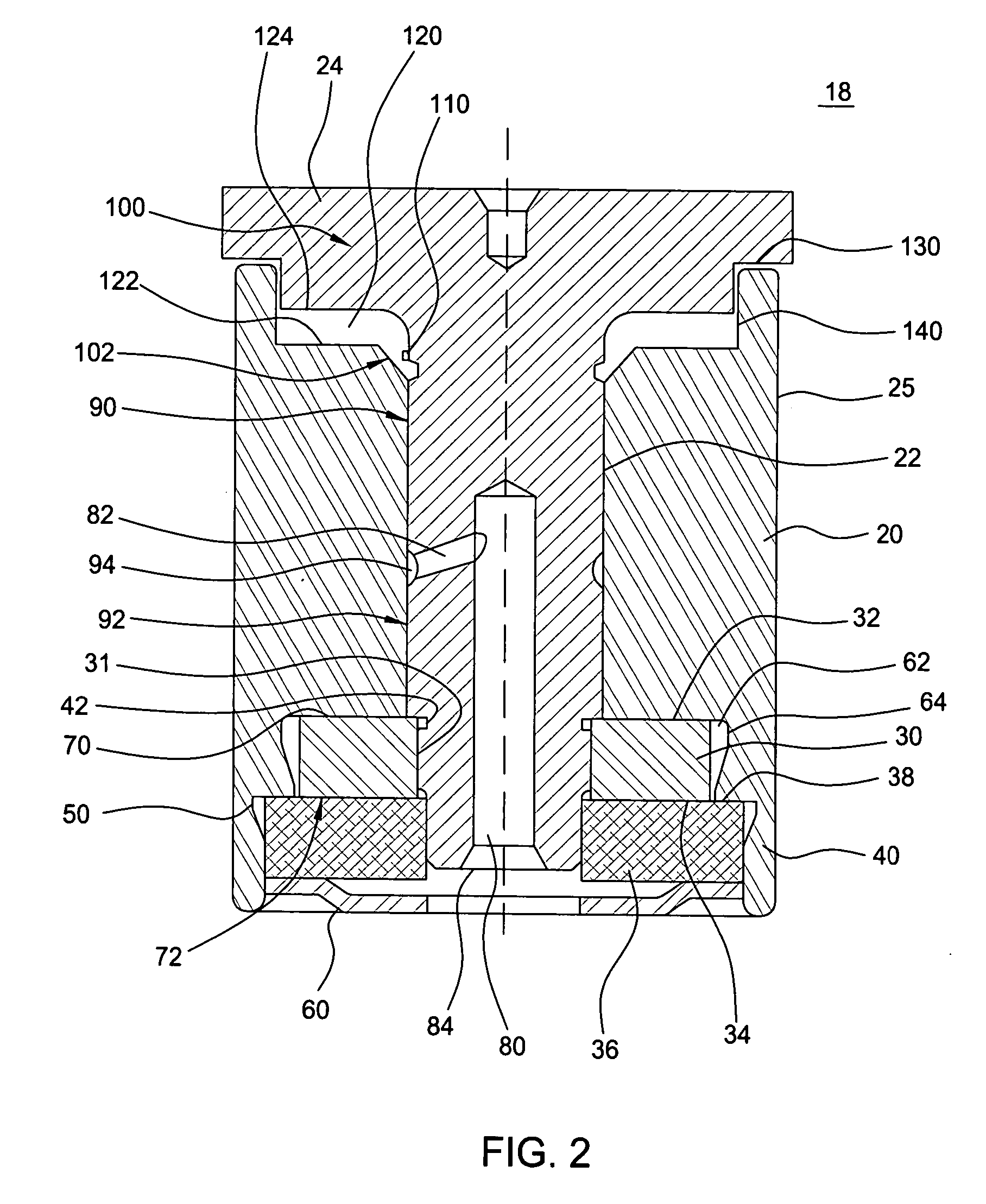
[0021]FIG. 2 is a first example of a hydrodynam...


PUM


Abstract

A hydrodynamic bearing having a shaft relatively rotatable with respect to a surrounding sleeve and having a thrust plate on one end thereof rotating in a recess of the sleeve. The shaft is preferably interrupted by a equi-pressure groove accessing a central reservoir in the shaft and having journal bearings defined by herringbone patterns above and below the groove to stabilize and provide stiffness to the cartridge. The stiffness of the cartridge is further enhanced by a thrust plate carried at one end of the shaft and rotating in a recess of the sleeve and being used to define thrust bearings on either surface.

Description

RELATED APPLICATIONS [0001] This application is related to and may be used in common with the invention disclosed in A-60203 / JAS, entitled “Vacuum Fill Technique for Hydrodynamic Bearing”, U.S. Ser. No. 08 / 503,568, filed Jul. 18, 1995, inventor: Parsoneault; A-60465 / JAS entitled “Absorbent Oil Barrier”, unfiled, inventor: Parsoneault; A-60464 / JAS entitled “Thrustbearing Built with Single Sided Grooved Plates”, unfiled, inventor: Leuthold; A-59788 / JAS entitled “Single Plate Hydrodynamic Bearing with Fluid Circulation Path and Self Balancing Fluid Level”, U.S. Ser. No. 08 / 278,754, filed Jul. 22, 1994, inventor: Leuthold, all of said applications being assigned to the assignee of the present invention and incorporated herein by reference.FIELD OF THE INVENTION [0002] The present invention relates to the field of hydrodynamic bearing assemblies, and especially to such assemblies adapted to have good stiffness and long useful life. BACKGROUND OF THE INVENTION [0003] Many motors, spindles...

Claims


Application Information

Patent Timeline
Patent Type & Authority Applications(United States)
IPC IPC(8): F16C17/10F16C33/10
CPCF16C17/026F16C33/107F16C17/10F16C17/107
Inventor NAGARATHNAM, LAKSHMANLEUTHOLD, HANSJENNINGS, DAVIDPARSONEAULT, NORBERTCLARK, WESLEY R.HEINE, GUNTER
Owner SEAGATE TECH LLC
Why Eureka
Try Eureka