
Hill ascent method

a technology of traction control and ascent method, which is applied in the direction of mechanical equipment, transportation and packaging, etc., can solve the problems of vehicle sitting, vehicle being required, and falling off,

Active Publication Date: 2019-04-09
JAGUAR LAND ROVER LTD
View PDF20 Cites 5 Cited by
  • Summary
  • Abstract
  • Description
  • Claims
  • Application Information

AI Technical Summary

Benefits of technology

The patent describes a transmission system that can shift between different speed ratios, making it suitable for both on-highway and off-highway use. Surprisingly, this transmission system has also been found to have advantages in addressing the problem of shifting failures when driving up hills.

Problems solved by technology

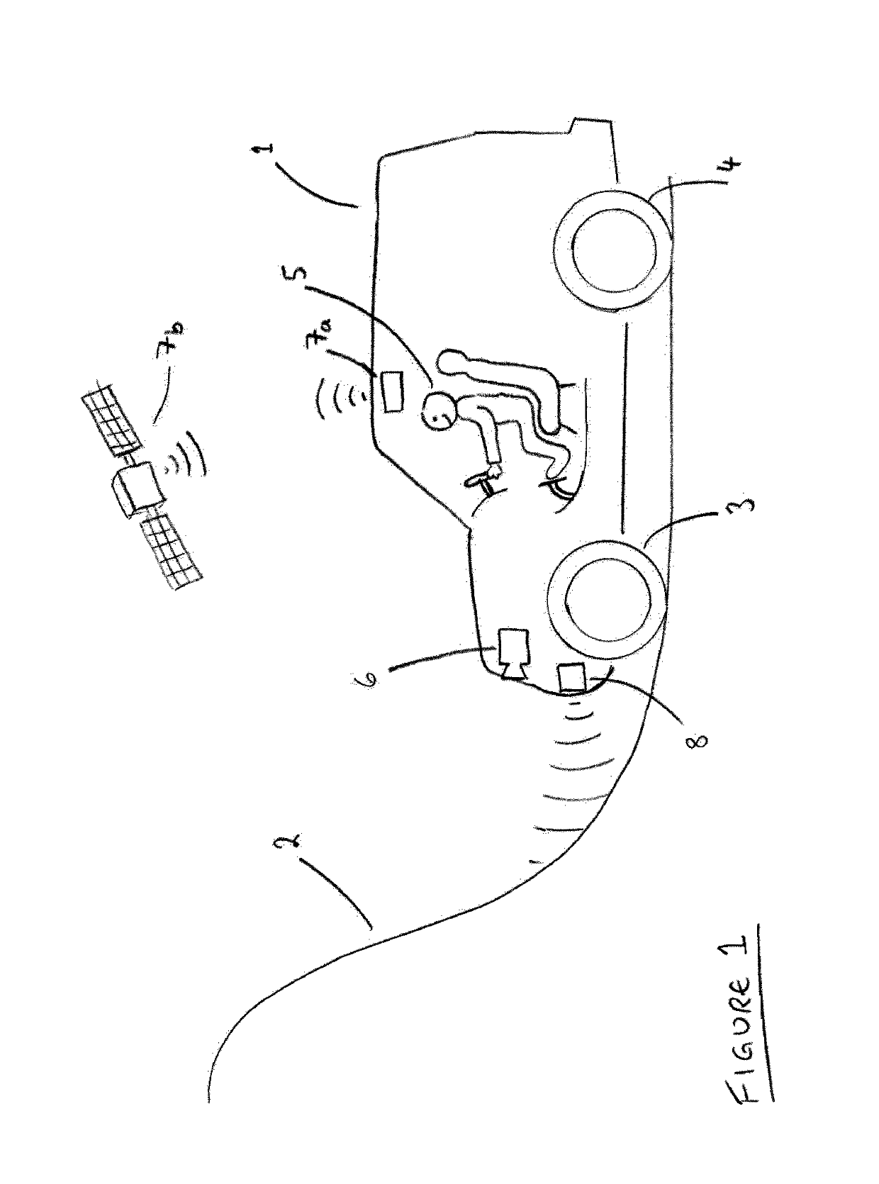
In particular, such vehicles may be required to make ascents on slopes comprising gradients that are particularly steep.
This may be as a result of insufficient power available to the vehicle from the engine or prime mover or, more usually, as a result of a loss of sufficient traction.
Alternatively, slope ascent may fail when the engine stalls.
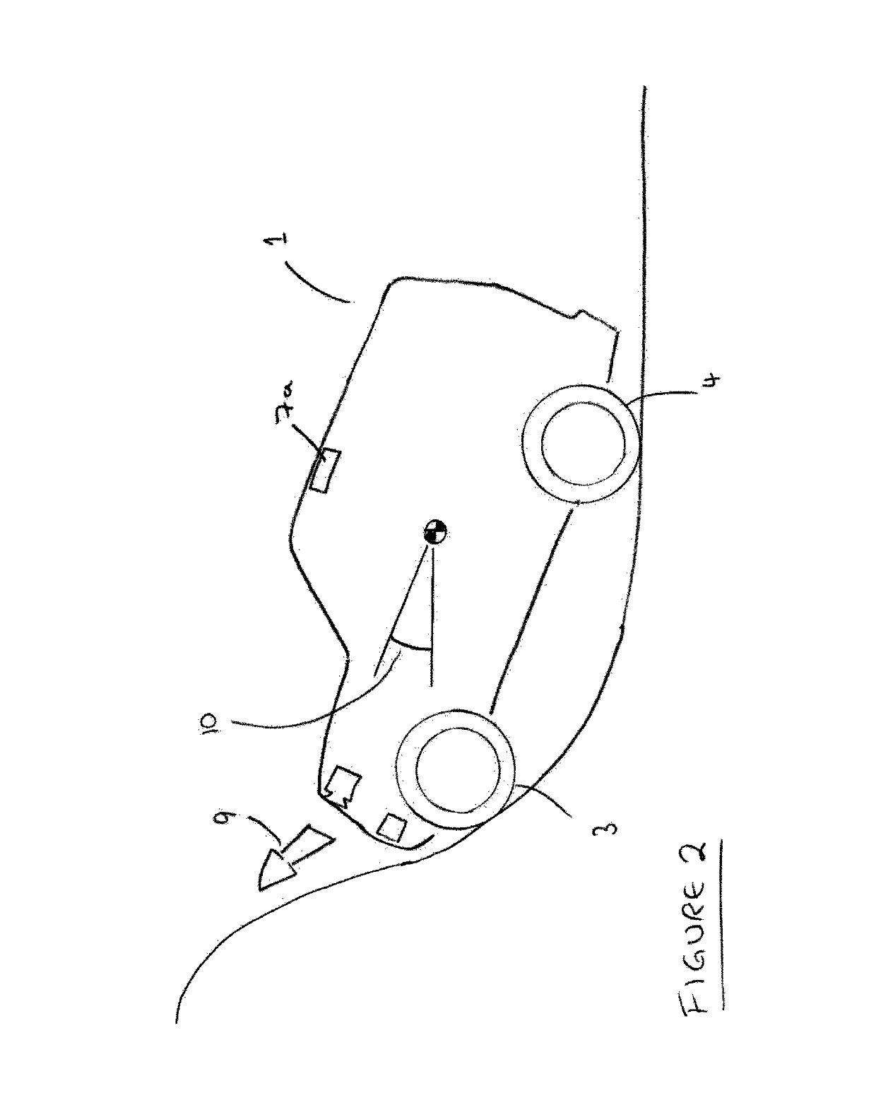
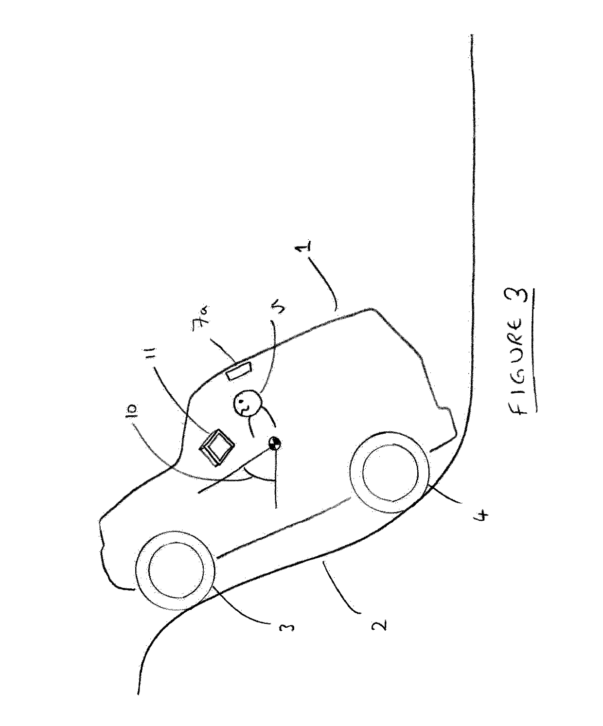
In either case, the failed ascent results in the vehicle sitting at rest, braked, on the slope.
In some circumstances, an engine of the vehicle may stall in this scenario.
Inexperienced drivers, however, may panic upon the realisation that a hill ascent has failed.
This is not advisable since, with no engine running, wheel brakes may not be as effective due to a lack of servo assistance, and a hill descent mode is also likely to be unavailable to assist in the descent.
Furthermore, vehicles tend to have a bias of braking to the front, so braking on descent in reverse tends to result in front wheel lock (unless a centre differential, where available, is locked), and an undesirable loss of lateral stability at the front end of the vehicle.
Some drivers may attempt to re-start the vehicle and continue to attempt to drive up the gradient, leading to a very difficult hill-start and most likely to further failure.

Method used


Image

  • Hill ascent method
  • Hill ascent method
  • Hill ascent method

Examples


Embodiment Construction

[0072]A method in accordance with an embodiment of the present invention is described herein with reference to the accompanying Figures.

[0073]FIG. 4 is a diagrammatic representation of a multi-speed constant mesh dual clutch transmission (DCT) having two inputs (21, 22), each with an associated friction clutch (A, B), one output (23), two or more forward speed ratios and two or more reverse speed ratios between said inputs and output, said speed ratios comprising individually selectable gear wheel trains, one of said forward speed ratios and one of said reverse speed ratios being associated with one input, one of said forward speed ratios and one of said reverse speed ratios being associated with the other input; said gearbox being adapted for pre-selection of a next required speed ratio in use, and for shifting from a current speed ratio to said next required speed ratio by shifting drive between said inputs; wherein said speed ratios are arranged for pre-selection to provide a shi...


PUM


Abstract

Aspects of the present invention relate to a method of using a transmission with multiple clutches in order to provide improved methods of traction control on a hill ascent. Embodiments provide for the use of power-shift, automatic or dual clutch gearboxes.

Description

TECHNICAL FIELD[0001]The present invention relates to a method of traction control for a vehicle, particularly a vehicle that is ascending a hill; a control system for implementing a control method, a powertrain equipped with such a control system, and a vehicle equipped with such a powertrain or control system.BACKGROUND OF THE INVENTION[0002]It is known to provide a vehicle with a traction control system, which may be provided with various off-road modes, particularly but not exclusively 4×4 vehicles, and particularly but not exclusively for use in such vehicles that may be required to operate off-road and / or in challenging conditions, said conditions being challenging either as a result of terrain type or of weather conditions. Such conditions (and their associated modes) may include Grass, Gravel and Snow (GGS), but may also include rocky terrain (or ‘rock crawl’), mud and ruts, ice, sand and / or steep gradients. In particular, such vehicles may be required to make ascents on slo...

Claims


Application Information

Patent Timeline
Patent Type & Authority Patents(United States)
IPC IPC(8): F16H61/02B60W10/18B60W50/14F16H59/66F16H61/16F16H61/688B60W10/113B60W30/18B60W10/11F16H59/44F16H59/54F16H59/74F16H59/50F16H59/24F16H59/14
CPCF16H61/0213B60W10/113B60W10/18B60W30/18036B60W30/18118B60W50/14F16H61/16F16H61/688B60W10/11F16H2312/09B60W2510/0604B60W2510/0657B60W2510/0661B60W2510/0666B60W2510/1005B60W2520/10B60W2520/16B60W2520/26B60W2520/28B60W2540/02B60W2540/04B60W2540/10B60W2540/12B60W2540/14B60W2550/12B60W2550/141B60W2550/142B60W2550/148B60W2710/1005B60Y2200/20F16H59/141F16H59/24F16H59/44F16H59/54F16H59/66F16H59/74F16H2059/147F16H2059/506F16H2059/663F16H2059/666F16H2059/743F16H2061/0234B60W10/02B60W10/184B60W40/076B60W40/105B60W2710/021B60W2710/18B60W2050/0075B60W2050/0043B60W2552/15B60W2552/40B60W30/14B60W30/18172B60W30/1884F16D48/062F16H3/006F16H61/0059F16H2312/04F16H2061/205B60W2540/21B60W2540/215B60W2552/05B60W2555/20
Inventor HOSE, MARKUS
Owner JAGUAR LAND ROVER LTD
Learn More