
Firearm-mounted defense spray foregrip system

a technology of firearms and foregrips, which is applied in the direction of white arms/cold weapons, butts, weapons, etc., can solve the problems of inconvenient and dangerous use, endanger the life of the operator or the individual confronted, and inconvenient and effective use, etc., to achieve convenient loading and reloading, convenient use, and convenient use

Active Publication Date: 2019-04-09
OHIO VALLEY DEFENSE LLC
View PDF24 Cites 4 Cited by
  • Summary
  • Abstract
  • Description
  • Claims
  • Application Information

AI Technical Summary

Benefits of technology

The system provides a safe, effective, and easy-to-use solution for deploying less-lethal weapons, maintaining muscle memory for operators and allowing for quick reloading, while ensuring compatibility with standard firearms and training systems, enhancing tactical control and deployment efficacy.

Problems solved by technology

Using an incapacitant, however, is inconvenient and dangerous when an operator is carrying a two-handed firearm.
In these situations, the operator is forced to choose between lethal and less-lethal weapons options, potentially endangering the operator's life or that of an individual confronting him or her.
To date, however, designs for doing so have been inadequate, and no such less-lethal weapon system has achieved significant adoption by any national law enforcement body.
Previous designs known in the art have either employed non-standard mechanisms that require additional training for use, have proven difficult to use, use a longitudinal mounting design, are not reloadable during use, or simply are not enabled.
However, the typical foregrip usually serves few other practical purposes, often simply being a hollow cavity where additional batteries or other tactical items might be stored.

Method used


Image

  • Firearm-mounted defense spray foregrip system
  • Firearm-mounted defense spray foregrip system
  • Firearm-mounted defense spray foregrip system

Examples


Embodiment Construction

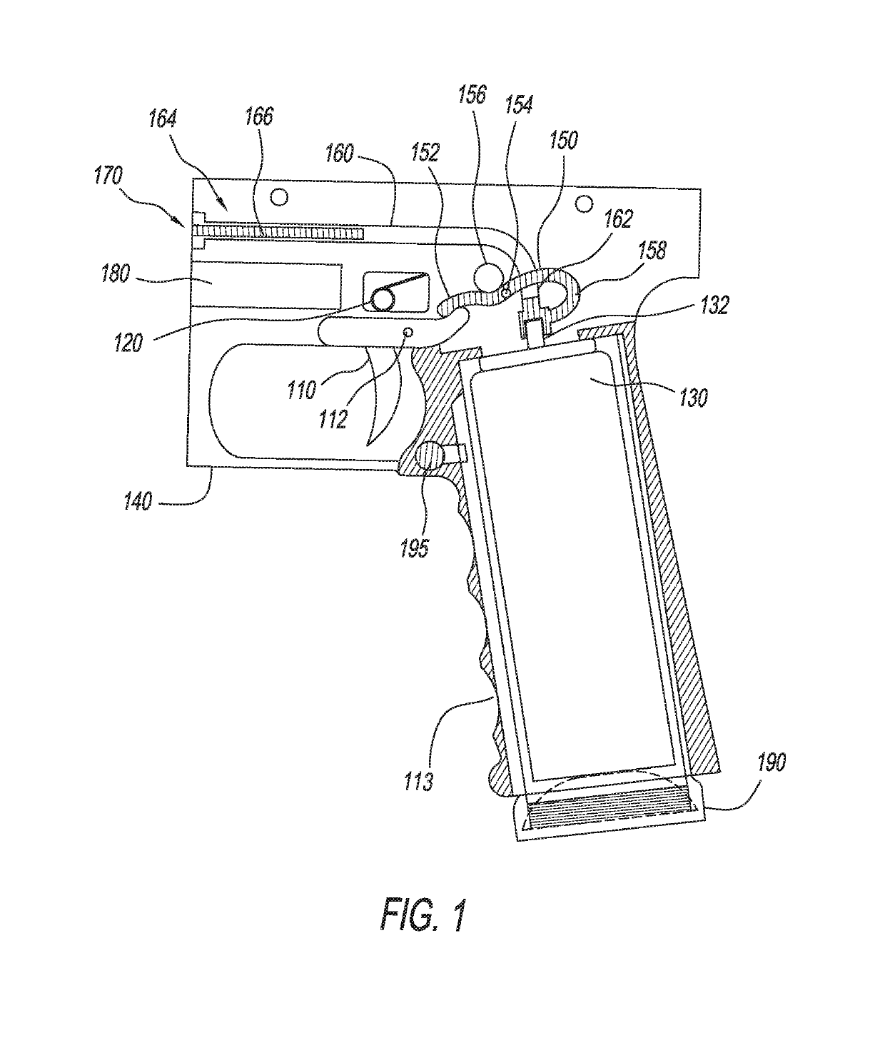
[0033]The detailed description of the disclosed device will be primarily, but not entirely limited to subcomponents, subsystems, and sub methods, of less-lethal weapons systems, including incapacitant media. Therefore, although not described in detail here, other essential features which are readily interpreted from or incorporated along with the disclosed invention shall be included as part of the device. The specification for the device provides specific examples to portray inventive steps, but which will not necessarily cover all possible embodiments commonly known to those skilled in the art. For example, the specific invention disclosed will not necessarily include all obvious features needed for operation, examples being materials specifications, metal / alloy composition and metal treatment parameters, sealing components, connecting hardware, and surface coatings, among other things.

[0034]The disclosed invention applies to any type of less-lethal weapon device that may be mount...


PUM


Abstract

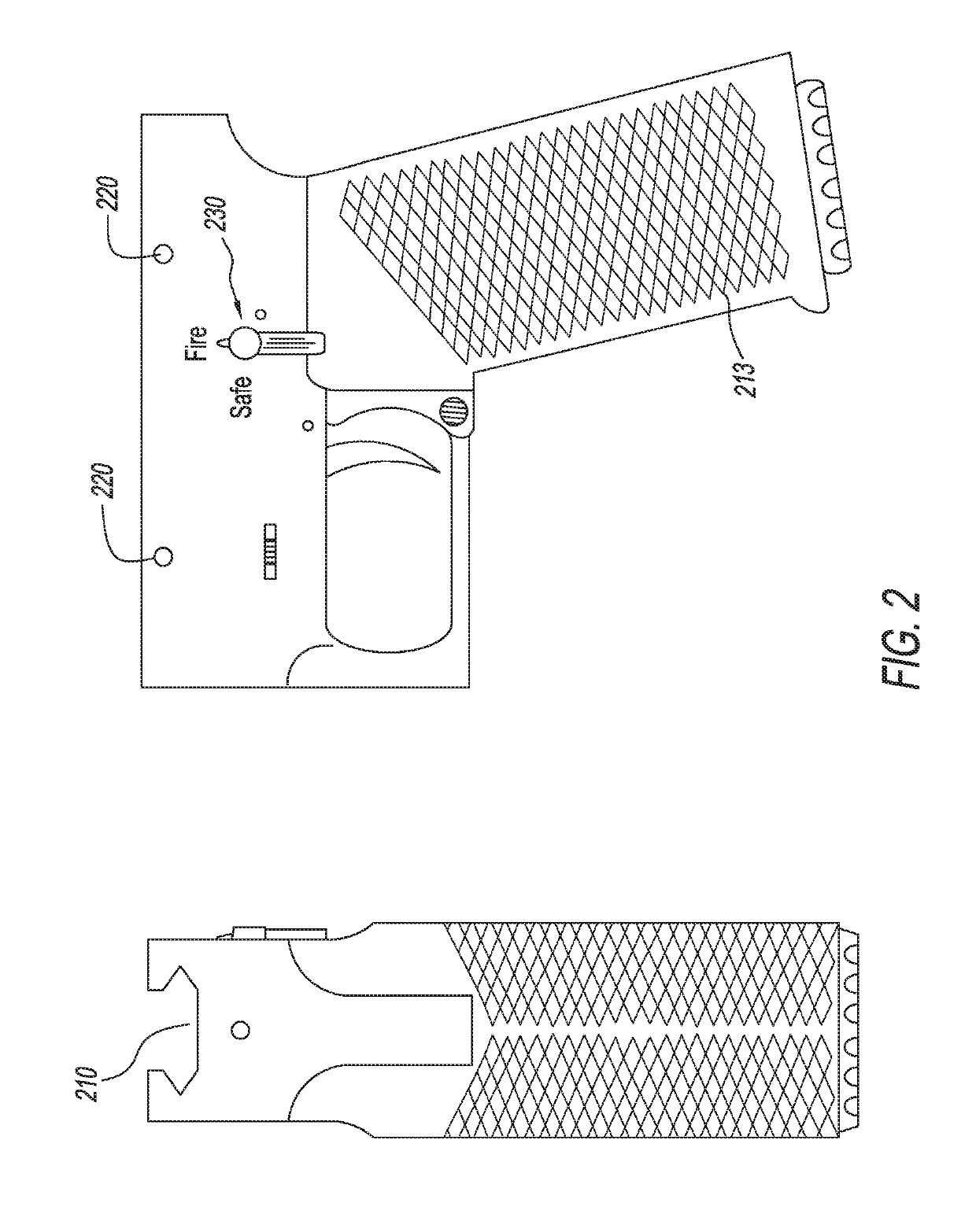
The disclosure is premised on the realization that despite the apparent convenience, safety and effectiveness possible by use of a less-lethal weapon incorporated into the foregrip of a two-handed weapon, no major police department, government agency, or military unit deploys such a system. This deficiency can be remedied by the disclosed device, which comprises a less-lethal weapon system that employs industry-standard components, and is effective and easy to use. The disclosed invention mounts a standard-size incapacitant canister in the handgrip portion of a foregrip. The foregrip is secured to the firearm by a standard rail system, and uses standard trigger and safety configurations. The canister magazine allows for efficient loading and reloading of the incapacitant, and the canister mounting angle allows for effective use. Further, some embodiments of the invention may include an accessory mounting area in which a tactical flashlight or laser may be mounted.

Description

STATEMENT REGARDING FEDERALLY SPONSORED RESEARCH OR DEVELOPMENT[0001]No federal funds were utilized for this invention.CROSS-REFERENCE TO RELATED APPLICATIONS[0002]The present application relates to U.S. Provisional Application No. 62 / 152,021, filed Apr. 23, 2015, the disclosure of which is hereby incorporated herein by reference in its entirety.BACKGROUND OF THE INVENTION[0003]Less-lethal weapons such as pepper-spray and other incapacitants are an essential part of the military and law enforcement arsenal. Using an incapacitant, however, is inconvenient and dangerous when an operator is carrying a two-handed firearm. In these situations, the operator is forced to choose between lethal and less-lethal weapons options, potentially endangering the operator's life or that of an individual confronting him or her. One solution for this problem is to mount an incapacitant dispenser on the firearm. To date, however, designs for doing so have been inadequate, and no such less-lethal weapon ...

Claims


Application Information

Patent Timeline
Patent Type & Authority Patents(United States)
IPC IPC(8): F41H9/10F41C23/16F41B9/00
CPCF41H9/10F41C23/16F41B9/0087F41B9/0071
Inventor GOSSON, MARKMILLER, CURTISNEWMAN, ANDREWRUFF, BRADLEY
Owner OHIO VALLEY DEFENSE LLC
Learn More