Portable hard surface cleaning appliance

a cleaning appliance and portability technology, applied in the direction of suction cleaners, domestic applications, suction nozzles, etc., can solve the problems of considerable manufacturing costs and achieve the effects of reducing manufacturing costs, facilitating the positioning of the holding member, and simplifying the construction design of the hard surface cleaning applian

Active Publication Date: 2019-04-16
ALFRED KARCHER GMBH & CO KG
View PDF10 Cites 6 Cited by
  • Summary
  • Abstract
  • Description
  • Claims
  • Application Information

AI Technical Summary

Benefits of technology

[0009]In the portable hard surface cleaning appliance in accordance with the invention, the dirty liquid tank is fixed in the tank accommodating compartment by at least one supporting element of the tank accommodating compartment engaging under the dirty liquid tank and two holding elements receiving between them an upper tank section of the dirty liquid tank. Such a configuration has the advantage that the requirements for the dimensional accuracy of the dirty liquid tank can be kept relatively low. It must be ensured that the width of the dirty liquid tank in its upper tank section corresponds to the distance between the two holding elements. This requirement can be met in a relatively simple way. For example, it may be provided that the dirty liquid tank forms a plastic part produced in a blow molding process. In contrast thereto, the tank accommodating compartment can be produced as a one-part or multi-part, in particular, two-part plastic molded part in an injection molding process, with the distance between the two holding elements corresponding to the width of the dirty liquid tank in the upper tank section. This requirement can be met, in particular, in the injection molding process with narrow dimensional tolerances in a cost-effective manner.
[0043]The following description of an advantageous embodiment of the invention will serve for further explanation in conjunction with the drawings.

Problems solved by technology

This requires a high dimensional accuracy of the dirty liquid tank and so manufacture of the hard surface cleaning appliance involves considerable costs.

Method used


Image

  • Portable hard surface cleaning appliance
  • Portable hard surface cleaning appliance
  • Portable hard surface cleaning appliance

Examples


Embodiment Construction

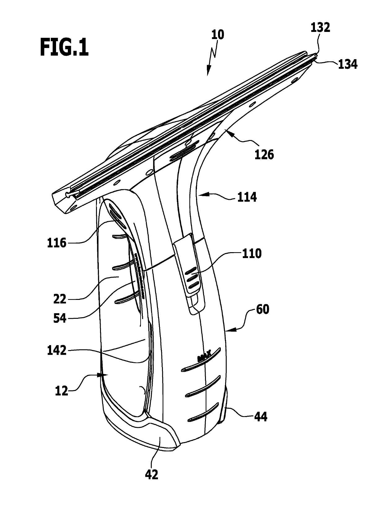
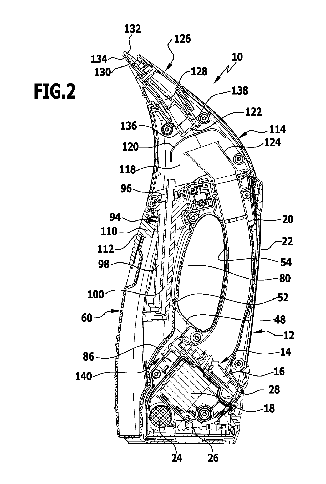
[0051]An advantageous embodiment of a portable hard surface cleaning appliance in accordance with the invention, denoted in its entirety by reference numeral 10, is shown schematically in the drawings. Liquid can be drawn off and sucked up from a hard surface, in particular, from a window pane by means of the portable hard surface cleaning appliance 10. The hard surface cleaning appliance 10 can be moved in the manner of a manual window squeegee along the hard surface by the user. The portable hard surface cleaning appliance in accordance with the invention therefore forms a window cleaning appliance.

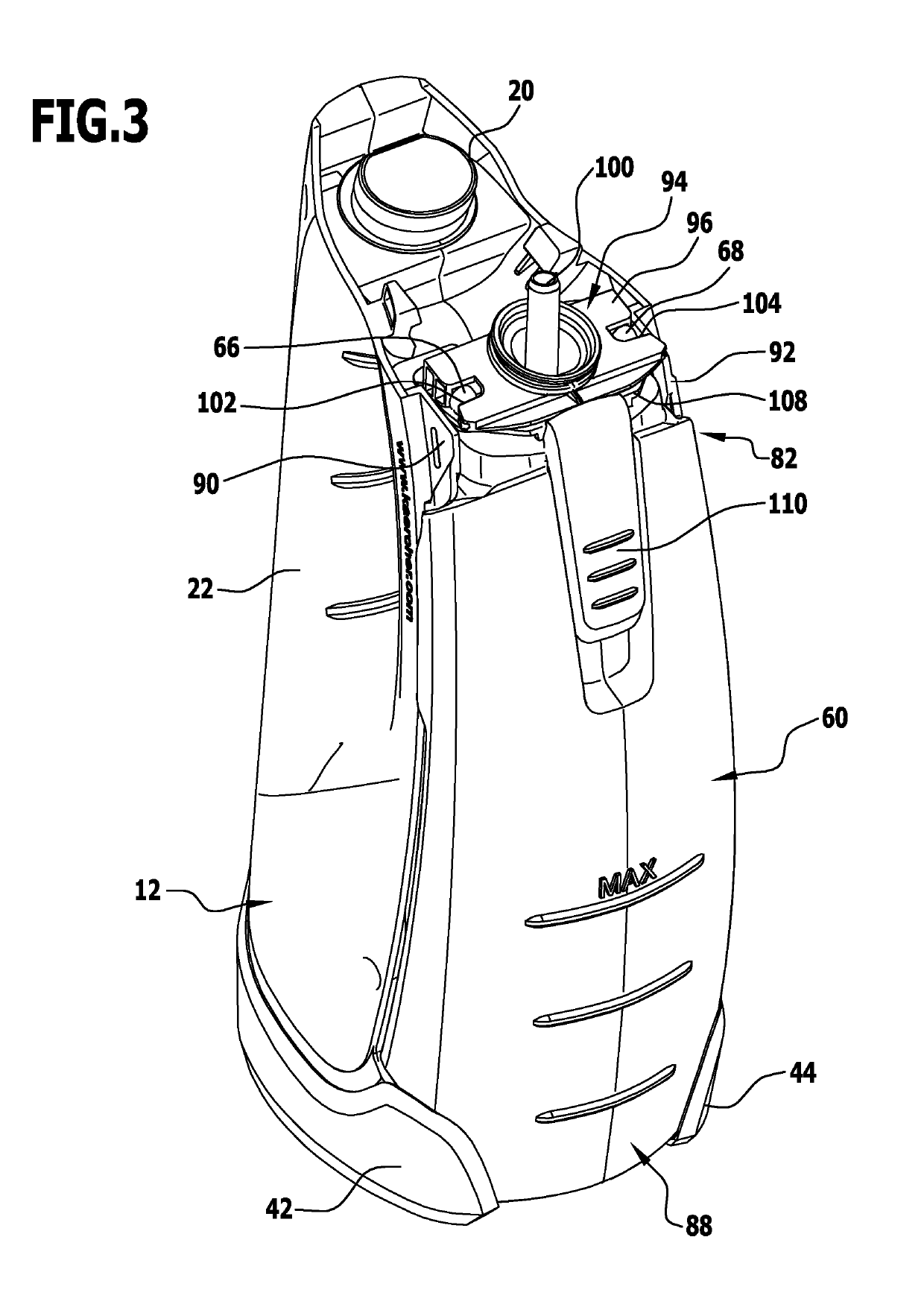
[0052]The hard surface cleaning appliance 10 comprises a base part 12 which is shown schematically, in particular, in FIG. 5. The base part 12 surrounds a suction unit 14 with a suction turbine 16 which is set in rotation by an electric motor 18. Air can be drawn in by the suction turbine 16 via an arcuately curved turbine inlet line 20. The turbine inlet line 20 runs through a grip 22 ...


PUM


Abstract

A portable hard surface cleaning appliance includes a suction nozzle with a suction opening on which at least one drawing-off lip is arranged, a suction unit in flow connection with the suction nozzle for sucking up a liquid-air mixture from the suction opening, a separation chamber arranged between the suction nozzle and the suction unit and having a separation device arranged within for separating liquid from the liquid-air mixture, and a tank accommodating compartment in which a dirty liquid tank for receiving the separated liquid is releasably held. The tank accommodating compartment includes at least one supporting element engaged under a lower tank section of the dirty liquid tank, and at least one holding element releasably connectable to an upper tank section of the dirty liquid tank. The portable hard surface cleaning appliance includes two holding elements which receive between them the upper tank section of the dirty liquid tank.

Description

CROSS-REFERENCE TO RELATED APPLICATIONS[0001]This application is a continuation of international application number PCT / EP2013 / 065247 filed on Jul. 18, 2013, which is incorporated herein by reference in its entirety and for all purposes.BACKGROUND OF THE INVENTION[0002]The invention relates to a portable hard surface cleaning appliance for drawing off and sucking up liquid from a hard surface, in particular, from a window pane, comprising a suction nozzle with a suction opening on which at least one drawing-off lip is arranged, a suction unit which is in flow connection with the suction nozzle for sucking up a liquid-air mixture from the suction opening, a separation chamber which is positioned in the flow path between the suction nozzle and the suction unit and in which a separation device is arranged for separating liquid from the liquid-air mixture, and a tank accommodating compartment in which a dirty liquid tank for receiving the liquid separated off in the separation chamber i...

Claims


Application Information

Patent Timeline
Patent Type & Authority Patents(United States)
IPC IPC(8): A47L5/24A47L11/40A47L1/05A47L9/06
CPCA47L5/24A47L1/05A47L11/40A47L9/06
Inventor STEWEN, CHRISTIANOBERLANDER, ANNEBARTEL, SANDRA
Owner ALFRED KARCHER GMBH & CO KG
Why Eureka
Try Eureka