Control device and control method for hybrid vehicle

a control device and hybrid technology, applied in the direction of hybrid vehicles, process and machine control, instruments, etc., can solve the problems of inability to properly control the rotational speed of the engine, and the inability to properly perform the shifting of the entire transmission

Inactive Publication Date: 2019-08-06
TOYOTA JIDOSHA KK
View PDF24 Cites 2 Cited by
  • Summary
  • Abstract
  • Description
  • Claims
  • Application Information

AI Technical Summary

Benefits of technology

[0005]The disclosure provides a control device and a control method for a hybrid vehicle that can properly perform shifting of an entire transmission combining a differential mechanism and a stepped transmission, regardless of the limitation of power of an electric power storage device.
[0007]With this configuration, the transmission torque of the shift progress side engagement device is set based on the power of the engine, the power necessary for progressing shifting of the differential mechanism and the stepped transmission, and the power of the electric power storage device such that limitation of the output torque of the first rotary machine and the output torque of the second rotary machine due to the limitation of the power of the electric power storage device when shifting the stepped transmission is suppressed. Consequently, the stepped transmission is shifted with the transmission torque of the shift progress side engagement device which takes into account the input-output balance of the respective powers. As a result, even if the power of the electric power storage device is limited when shifting the stepped transmission, desired output torque of the first rotary machine and desired output torque of the second rotary machine tend to be obtained, so that control can be properly performed so as to cause the change rate of the rotational speed of the engine to reach the target value. Therefore, shifting of the entire transmission combining the differential mechanism and the stepped transmission can be properly performed regardless of the limitation of the power of the electric power storage device.
[0009]With this configuration, shifting of the stepped transmission that further takes into account the input-output balance of the respective powers is performed. Consequently, shifting of the entire transmission can be more properly performed.
[0011]When the transmission torque of the shift progress side engagement device is set based on numerical values themselves of the respective powers, a predetermined relationship (map) becomes high dimensional, and therefore, adaptation becomes complicated. In contrast, according to the above-described configuration, by setting the transmission torque of the shift progress side engagement device by means of classifications using the plurality of levels corresponding to the magnitudes of each of the respective powers (i.e. by decreasing the number of arguments), the predetermined relationship can be made low dimensional to simplify adaptation.
[0013]With this configuration, the power-on downshift of the stepped transmission that is difficult in shift control compared to the power-on upshift of the stepped transmission can be properly performed. In this way, since the number of arguments can be changed according to the type of shift (e.g. according to the degree of difficulty of shift control), adaptation can be more simplified as shift control becomes easier.
[0015]With this configuration, the same effect as the above-described control device can be obtained.

Problems solved by technology

If power of the electric power storage device is small when shifting the stepped transmission, output torque of the first rotary machine and output torque of the second rotary machine are limited due to the limitation of the power of the electric power storage device.
Then, desired output torque of the first rotary machine or desired output torque of the second rotary machine is not obtained when shifting the stepped transmission, so that the change rate of the rotational speed of the engine may not be properly controlled to its target value.
Since the change rate of the rotational speed of the engine indicates the state of progress of shifting of the entire transmission combining the differential mechanism and the stepped transmission, if the change rate of the rotational speed of the engine cannot be properly controlled to its target value, this means that the shifting of the entire transmission cannot be properly performed.
The electronic control unit is configured to set transmission torque of the shift progress side engagement device based on power of the engine, power necessary for progressing shifting of the differential mechanism and the stepped transmission, and power of the electric power storage device, such that limitation of output torque of the first rotary machine and output torque of the second rotary machine due to limitation of the power of the electric power storage device when shifting the stepped transmission is suppressed.
When the transmission torque of the shift progress side engagement device is set based on numerical values themselves of the respective powers, a predetermined relationship (map) becomes high dimensional, and therefore, adaptation becomes complicated.

Method used


Image

  • Control device and control method for hybrid vehicle
  • Control device and control method for hybrid vehicle
  • Control device and control method for hybrid vehicle

Examples


Embodiment Construction

[0025]A rotational speed w of each of the rotating members (e.g. the engine, the first rotary machine, the second rotary machine, the rotary elements of the differential mechanism, the intermediate transmission member, and the rotary elements of the stepped transmission) may corresponds to an angular velocity of the rotating member, and the change rate of the rotational speed ω is the time change rate, i.e. the time differential, of the rotational speed ω and thus is an angular acceleration dω / dt of the rotating member, while the angular acceleration dω / dt may be given by {acute over (ω)} in a numerical formula.

[0026]Hereinbelow, an embodiment of the disclosure will be described in detail with reference to the drawings.

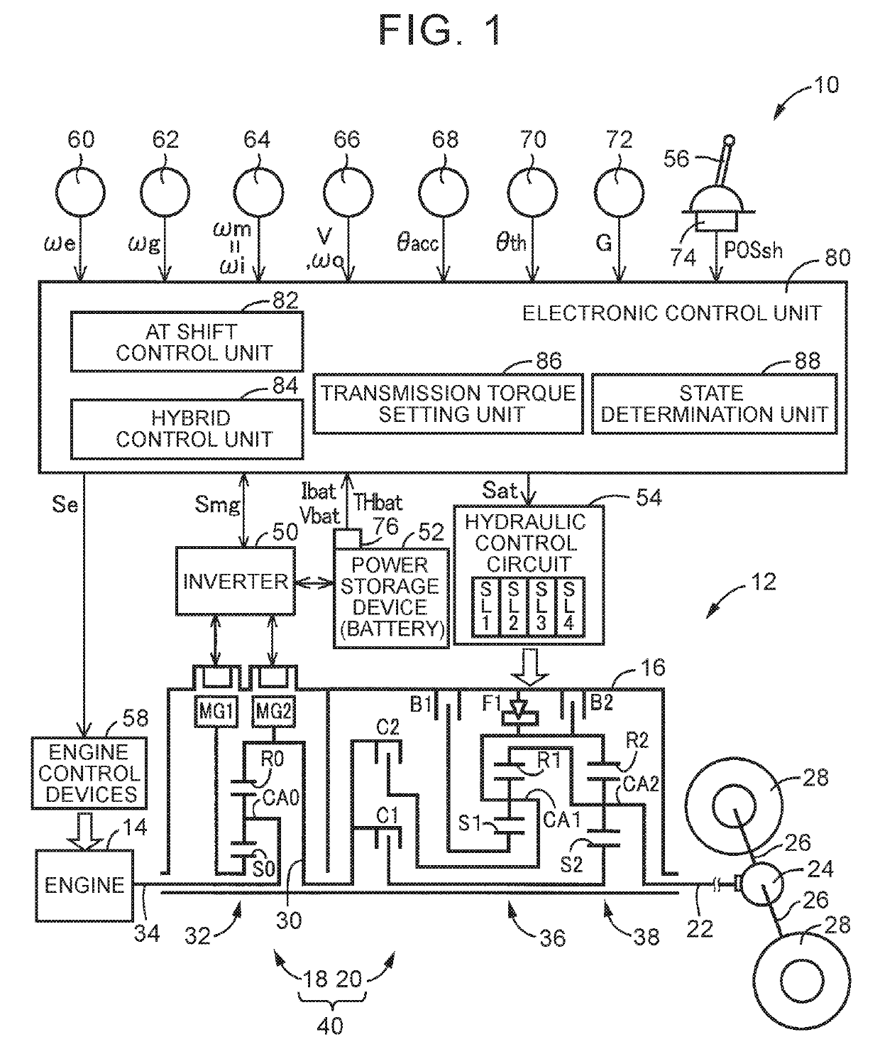
[0027]FIG. 1 is a diagram for explaining a schematic configuration of a vehicle driving system 12 included in a vehicle 10 to which the disclosure is applied, and is also a diagram for explaining control functions and a main part of a control system for various contro...


PUM


Abstract

Transmission torque of a shift progress side engagement device is set based on engine power, shift progressing power, and battery power such that MG1 torque and MG2 torque are limited due to the limitation of the battery power when shifting a stepped transmission is suppressed. The stepped transmission is shifted with the transmission torque which takes into account the input-output balance of the respective powers.

Description

INCORPORATION BY REFERENCE[0001]The disclosure of Japanese Patent Application No. 2016-231853 filed on Nov. 29, 2016 including the specification, drawings and abstract is incorporated herein by reference in its entirety.BACKGROUND1. Technical Field[0002]The disclosure relates to a control device and a control method for a hybrid vehicle including a differential mechanism and a stepped transmission disposed in series.2. Description of Related Art[0003]Japanese Patent Application Publication No. 2014-223888 (JP 2014-223888 A) discloses a control device for a hybrid vehicle including an engine, a differential mechanism, a second rotary machine, a stepped transmission and an electric power storage device. In JP 2014-223888 A, the differential mechanism has three rotary elements to which the engine, a first rotary machine, and an intermediate transmission member are respectively coupled. The second rotary machine is coupled to the intermediate transmission member in a power transmittable...

Claims


Application Information

Patent Timeline
Patent Type & Authority Patents(United States)
IPC IPC(8): B60L9/00G05D1/00G05D3/00G06F7/00G06F17/00B60W20/30B60K6/40B60K6/547B60K6/365B60K6/445B60W10/06B60W10/08B60W10/115B60W10/26B60W30/19F16H61/04F16H61/02B60L50/16
CPCB60W20/30B60K6/40B60K6/445B60K6/547B60W10/06B60W10/08B60W10/115B60W10/26B60W30/19F16H61/0437B60K6/365Y02T10/7258B60W2510/0657B60W2510/105B60W2710/027B60W2710/0677B60W2710/10F16H61/0213B60K6/36B60W10/11B60W20/00Y02T10/62Y02T10/72B60W10/10B60W10/12B60W2710/0666B60W2710/105B60Y2200/92
Inventor KOBAYASHI, NOBUFUSAYOSHIKAWA, MASATOKUMAZAKI, KENTA
Owner TOYOTA JIDOSHA KK
Why Eureka
Try Eureka