Absolute rotary encoder

a rotary encoder and encoder technology, applied in the field of absolute rotary encoders, can solve the problems of incorrect position reading, high cost, and inability to meet the requirements of many applications of optical rotary encoders, and achieve the effect of reliable measurement and easy integration with other electronics

Active Publication Date: 2019-04-16
IP2IPO INNOVATIONS LTD
View PDF13 Cites 4 Cited by
  • Summary
  • Abstract
  • Description
  • Claims
  • Application Information

AI Technical Summary

Benefits of technology

[0012]The rotary encoder of the present invention can determine an absolute position around the rotational axis of the encoder. If the magnetised element were to rotate around the rotational axis of the encoder, the magnetic field detected by each magnetic sensor arrangement would fluctuate due to the presence of multiple magnetic pole pairs in each magnetic track and the ensuing variations in magnetic polarization. As the number of pole pairs within each track within the subtended angle θ around the axis of the rotary encoder, i.e. the number of magnetic pole pairs, in each track are different and have a greatest common factor of one, combining the measurements from the two magnetic sensor arrangements can give a unique value, which is corresponded to an absolute position of the rotary encoder. The present invention has an efficient architecture; the arrangement of the two magnetic tracks on different surfaces of the magnetised element means a magnetic rotary encoder can be manufactured which is smaller than those currently available, but with the same resolution. The present invention could also be manufactured with a hollow shaft through which wires could be passed, without the device being any larger than those currently available. This could be advantageous for applications in which multiple rotary encoders are joined in series.
[0013]Preferably, the first and second surfaces of the magnetised element are perpendicular to one another. Furthermore, in preferred embodiments the magnetic sensor arrangements are orientated perpendicular to one another. This architecture ensures the overall size of the encoder is minimised.
[0014]In preferred embodiments, each magnetic track forms a circular arc. The arc may be complete or incomplete, depending on the range of measurement required. In preferred embodiments, the arc is complete, allowing measurement around a full circle. For example, the magnetised element may preferably be a circular ring arranged coaxially around the axis of the rotary encoder. Furthermore, in preferred embodiments the angle θ is equal to 360 degrees. The geometry of these preferred embodiments allows the encoder to measure the absolute position through the full 360 degree range, whilst still allowing for a small device with the option for a hole in the magnetised element through which wiring can be passed. In preferred embodiments, each sensor arrangement comprises a plurality of sensors. Preferably, the sensors in the first sensor arrangement are separated by an angular distance ϕ around the axis of the rotary encoder which is the same as an angular width of the poles within the first magnetic track. Similarly, the sensors in the second sensor arrangement may preferably be separated by an angular distance ϕ′ around the axis of the rotary encoder which is the same as an angular width of the poles within the second magnetic track. In this manner each sensor can be suitably located with respect to the magnetic pole pairs of the corresponding magnetic track.
[0016]Preferably, the sensors are hall sensors. These sensors provide reliable measurements that can be readily integrated with other electronics.

Problems solved by technology

Optical rotary encoders are generally high resolution and high accuracy devices, but tend to be expensive.
In addition to their cost, optical encoders are not suited to many applications because of their lack of robustness; they must be precisely aligned and are particularly sensitive to contaminants such as dirt or moisture, which can cause optical errors and lead to incorrect position readings.
However, such devices have a relatively low resolution and the layout of the components precludes the possibility of the encoder having a hollow shaft suitable for passing wiring through.
Although addressing the problem of low resolution, wiring still cannot be passed through the shaft of the encoder due to the presence of the on-axis magnet.
Consequently, the use of multiple magnetic tracks increases the thickness or width of the magnetised element of the encoder, and thus increases the overall size of the encoder.

Method used


Image

  • Absolute rotary encoder
  • Absolute rotary encoder
  • Absolute rotary encoder

Examples


Embodiment Construction

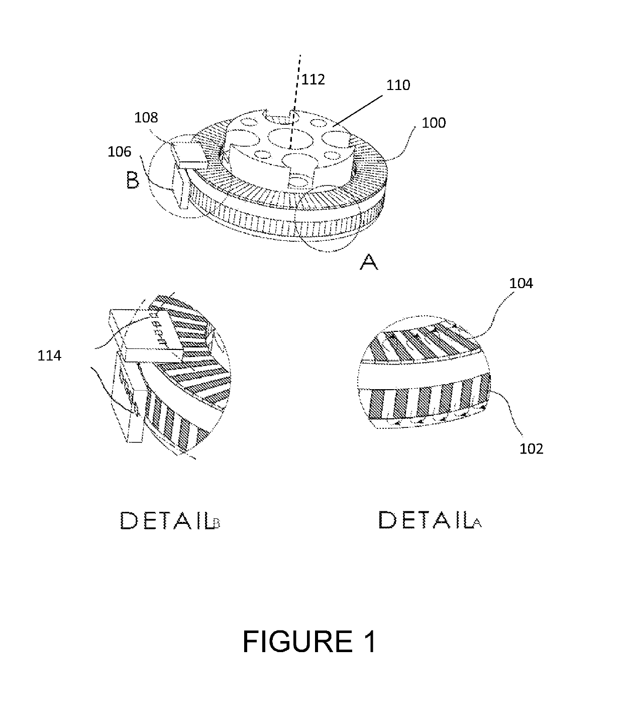
[0023]Referring to FIG. 1, there is shown an absolute rotary encoder according to a preferred embodiment of the present invention. Absolute position of the rotary encoder is measured around the rotational axis of the encoder 112. The absolute rotary encoder of this embodiment comprises: a magnetised element 100; first and second magnetic tracks 102 and 104; and first and second magnetic sensor arrangements 106 and 108. In this embodiment, the absolute rotary encoder also comprises a hollow shaft 110 which is arranged coaxially with the rotational axis of the encoder 112.

[0024]The magnetised element 100 in this embodiment is a circular magnetised ring 100, although alternative geometries may be used. The magnetised ring 100 is arranged coaxially around the rotational axis 112 and hollow shaft 110, such that the hollow shaft 110 protrudes through the hole at the centre of the magnetised ring 100. The magnetised ring 100 is imprinted with a first magnetic track 102 and a second magneti...


PUM


Abstract

A rotary encoder for measuring absolute rotation around an axis of the rotary encoder, comprising: a magnetised element comprising first and second surfaces at an angle to one another; a first magnetic track provided on the first surface and a second magnetic track provided on the second surface, wherein the first and second magnetic tracks subtend an angle θ around the axis of the rotary encoder, wherein each magnetic track comprises a number of magnetic pole pairs, a magnetic pole pair being formed of two poles defining regions of opposite magnetic polarization, wherein the number of magnetic pole pairs in each track are different and have a greatest common factor of one; and first and second magnetic sensor arrangements, the first magnetic sensor arrangement arranged to detect a magnetic field of the first magnetic track and the second magnetic sensor arrangement arranged to detect a magnetic field of the second magnetic track, wherein the magnetic sensor arrangements are rotatably coupled to the magnetised element around the axis of the rotary encoder.

Description

[0001]This Application is a U.S. National stage of PCT / GB2015 / 053621 filed Nov. 27 2015, and claims priority to 1421196.5 (GB) filed Nov. 28, 2014, which are incorporated herein by reference.FIELD OF THE INVENTION[0002]The present invention relates to the field of rotary encoders. In particular, the present invention relates to absolute rotary encoders.BACKGROUND TO THE INVENTION[0003]A rotary encoder is a device which measures the angular position of a shaft around a rotational axis of the encoder. There are two types of rotary encoders: incremental, which determine the relative change in position, or motion, of the shaft; and absolute, which determine the absolute position of the shaft around the rotational axis of the encoder. Absolute rotary encoders are widely used in a range of applications and technical fields such as robotics, medical devices, telescopes and CNC machines.[0004]There are many types of absolute rotary encoder devices (e.g. magnetic, capacitive, mechanical, and...

Claims


Application Information

Patent Timeline
Patent Type & Authority Patents(United States)
IPC IPC(8): G01D5/14G01D5/249G01R33/07G01R33/09G01D5/245G01R33/025G01B7/30G01B7/00
CPCG01D5/145G01D5/2497G01D5/2452
Inventor LIU, JINDONGYANG, GUANG-ZHONG
Owner IP2IPO INNOVATIONS LTD
Why Eureka
Try Eureka