
Image display apparatus, external device, image display method, and image display system

a technology of image display apparatus and external devices, which is applied in the direction of television systems, selective content distribution, instruments, etc., can solve the problems of difficult operation for users, user needs to learn a new operation method, and the method of directly operating the image display apparatus is not convenient for users of external devices installed in a place apart from the image display apparatus, etc., to achieve the effect of easy change of a setting

Active Publication Date: 2019-04-23
SHARP KK
View PDF3 Cites 0 Cited by
  • Summary
  • Abstract
  • Description
  • Claims
  • Application Information

AI Technical Summary

Benefits of technology

Enables easy and convenient setting changes for external devices without the need for a special control system, simplifying operations and reducing complexity, especially when multiple devices with different connection methods are involved.

Problems solved by technology

However, a method of directly operating the image display apparatus is not convenient for a user of an external device installed in a place apart from the image display apparatus.
In a case of an operation method using the remote controller as well, it is difficult for the user to perform the operation immediately unless the remote controller is on hand, so that the user needs to ask another user to pass the remote controller.
Further, in a case where the image display apparatus to which the external device is connected or the attached remote controller has a type different from a type with which the user is familiar, there may be a problem that the user needs to newly learn an operation method.
In particular, in a case where a plurality of external devices are connected to the image display apparatus by different connection methods, it is necessary to construct a system according to the respective connection methods, thus causing a problem that the system is very complicated.

Method used


Image

  • Image display apparatus, external device, image display method, and image display system
  • Image display apparatus, external device, image display method, and image display system
  • Image display apparatus, external device, image display method, and image display system

Examples


embodiment 1

100>

[0021]An image display system 100 according to Embodiment 1 of the disclosure will be described,

[0022]Note that, though a case of switching of an image will be exemplarily described in the following embodiment as an example of a change of a setting that is determined in advance, the disclosure is applicable not only to switching of an image but also to setting of contrast, luminance, or the like of an image and a change of an image such as rotation of the image.

[0023]The disclosure is also applicable not only to setting of an image but also to setting of increasing or decreasing a sound volume or switching MUTE or a color mode, and setting of turning on or off setting of a network.

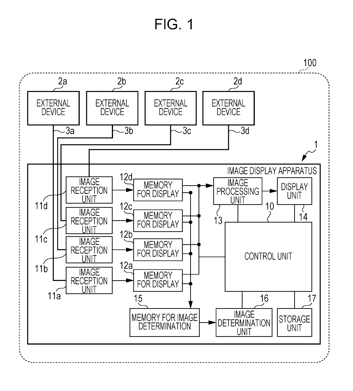
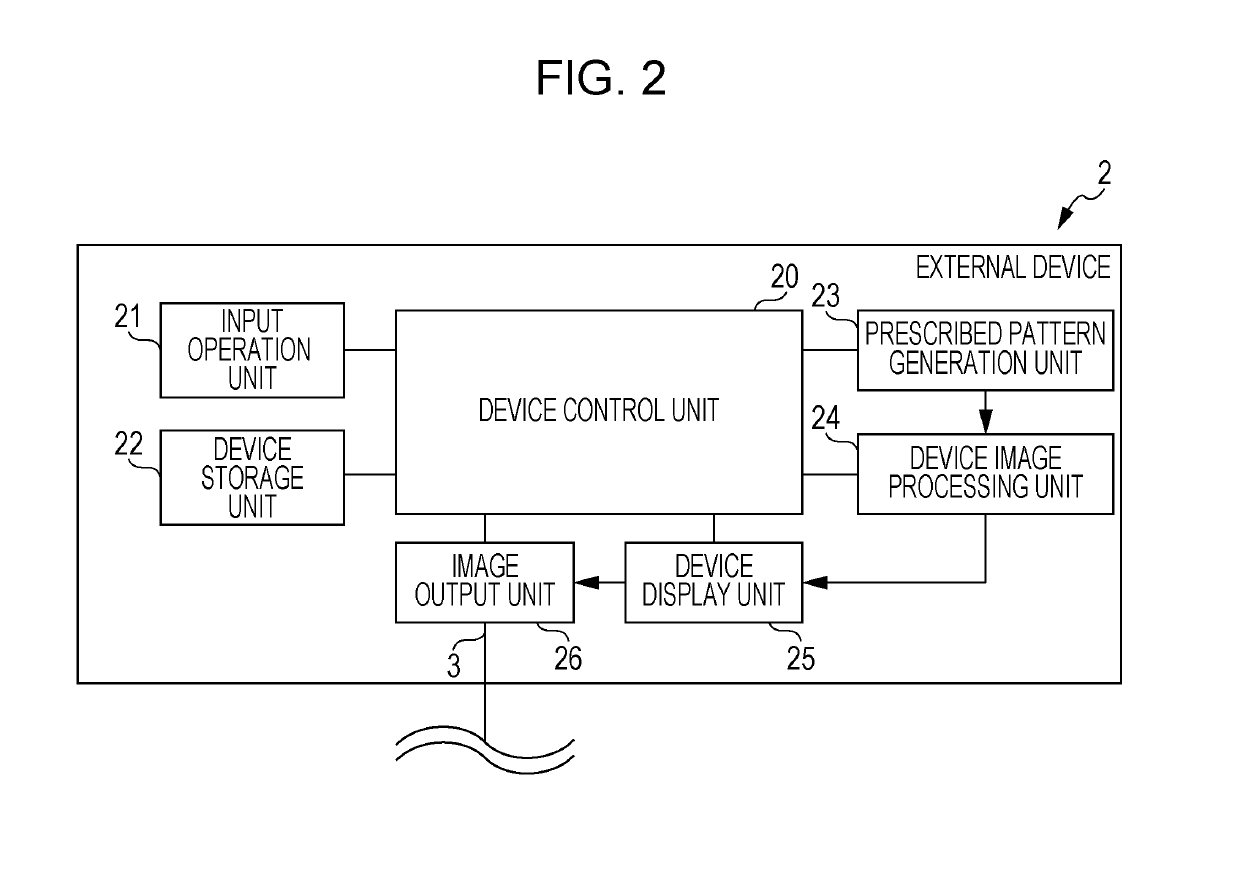
[0024]A configuration of the image display system 100 of the disclosure will be described with reference to FIGS. 1 and 2.

[0025]FIG. 1 is a block diagram illustrating a schematic configuration of the image display system 100 according to the disclosure and FIG. 2 is a block diagram illustrating a schem...

embodiment 2

[0109]Next, procedure of an image switching operation in the external device 2 for an image to be displayed on the display unit 14 of the image display apparatus 1 according to Embodiment 2 of the disclosure will be described with reference to FIGS. 7A to 7C.

[0110]FIGS. 7A to 7C are explanatory views illustrating a specific example of the image switching operation in the external device 2 for the image to be displayed on the display unit 14 of the image display apparatus 1 according to Embodiment 2 of the disclosure. FIGS. 7A to 7C are explanatory views illustrating a series of procedure of the image switching operation in the external device 2.

[0111]In Embodiment 1, the list 202 for an operation of the application for switching an input of an image is displayed in the predetermined region of the device display unit 25 in a fixed manner.

[0112]On the other hand, in Embodiment 2, as illustrated in FIG. 7A, when the application starts, a list 203 that is able to be moved by dragging is...

embodiment 3

[0116]Next, procedure of an image switching operation in the external device 2 for an image to be displayed on the display unit 14 of the image display apparatus 1 according to Embodiment 3 of the disclosure will be described with reference to FIGS. 8A to 8C.

[0117]FIGS. 8A to 8C are explanatory views illustrating a specific example of the image switching operation in the external device 2 for the image to be displayed on the display unit 14 of the image display apparatus 1 according to Embodiment 3 of the disclosure. FIGS. 8A to 8C are explanatory views illustrating a series of procedure of the image switching operation in the external device 2.

[0118]As illustrated in FIG. 8A, in Embodiment 3, a list 204 for an operation of the application for switching an input of an image is displayed in a predetermined region of the device display unit 25, similarly to Embodiment 1.

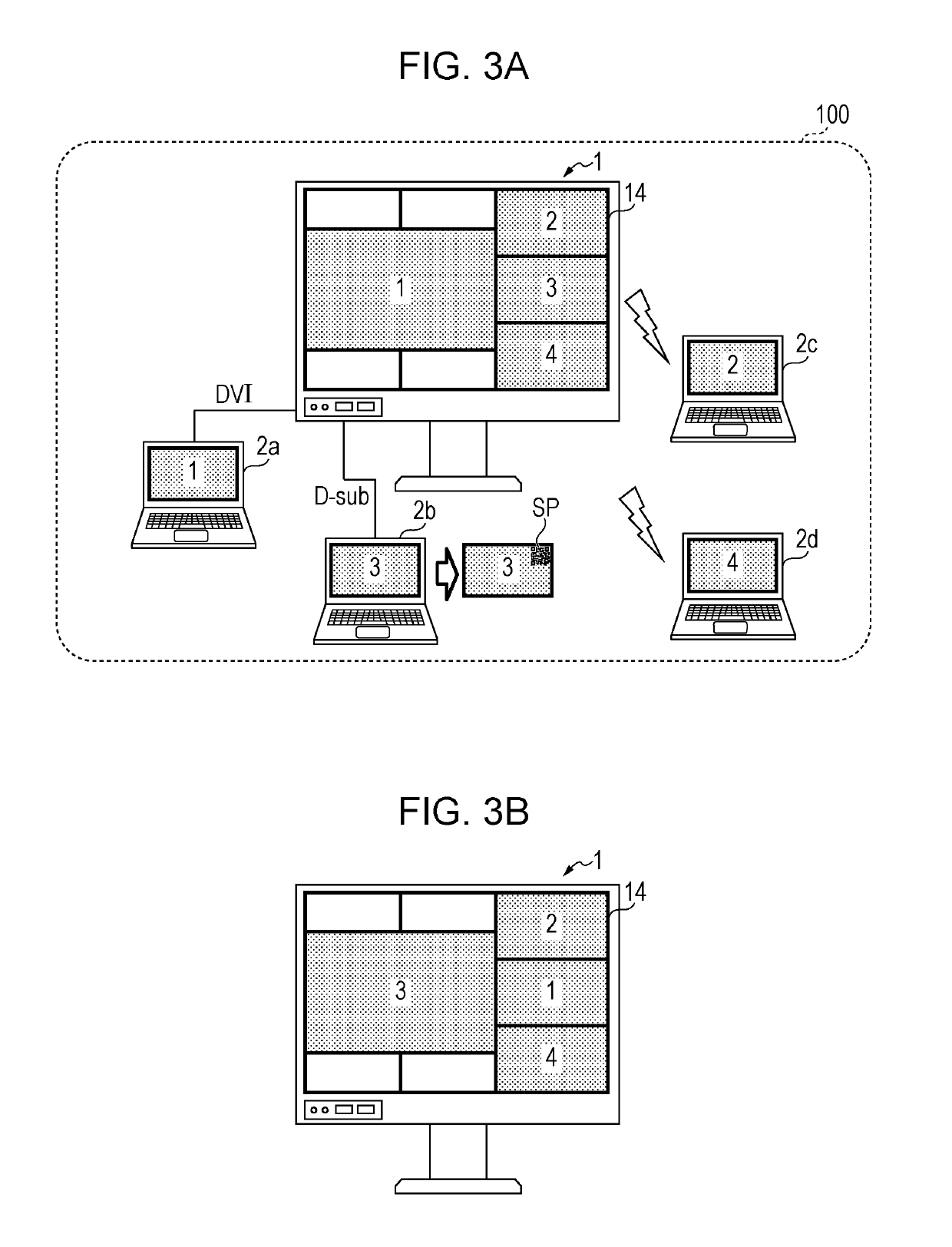
[0119]A difference from Embodiment 1 lies in that a prescribed pattern SP is displayed in a predetermined region of ...


PUM


Abstract

An image display apparatus includes an image reception unit that receives image data from an external device, a display unit that displays an image related to the image data, a setting changing unit that changes, in accordance with an instruction determined in advance, a setting determined in advance, an image determination unit that determines whether or not a prescribed pattern determined in advance is included in the image related to the image data, a storage unit that holds the instruction in association with the prescribed pattern in advance, and a control unit that, when the image determination unit determines that the prescribed pattern is included in the image related to the image data, causes the setting changing unit to change the setting in accordance with the instruction associated with the prescribed pattern.

Description

BACKGROUND1. Field[0001]The present disclosure relates to an image display apparatus, an external device, an image display method, and an image display system.2. Description of the Related Art[0002]An existing function of, in a case where one or more external devices such as personal computers (PCs) are connected to an image display apparatus such as a display apparatus, switching videos or images (hereinafter, “images”) input from two or more external devices or an image input from one or more external devices and an image of a main body of the image display apparatus and displaying the images in one screen of a display unit of the image display apparatus has been known. There also have been known a Picture By Picture (PBP) function of arranging and displaying such images in two or more small screens, a Picture In Picture (PIP) function of displaying a small screen in a large main screen, and the like.[0003]In a case where an operation of changing an image input from an external de...

Claims


Application Information

Patent Timeline
Patent Type & Authority Patents(United States)
IPC IPC(8): H04N5/45G09G5/00H04N21/431H04N21/462
CPCH04N5/45G09G5/00H04N21/4316H04N21/4622H04N21/4104H04N21/4312H04N21/647H04N21/8146G06F3/1438G09G5/14G09G2370/12G09G2370/16G09G2370/20H04N21/4858
Inventor YASUTA, AKIRA
Owner SHARP KK
Learn More