Adjusted pedal

Active Publication Date: 2019-04-30
CHEN CHUNG I
View PDF8 Cites 0 Cited by
  • Summary
  • Abstract
  • Description
  • Claims
  • Application Information

AI Technical Summary

Benefits of technology

[0006]An object of the present invention is to provide an adjusted pedal, which has simple

Problems solved by technology

Moreover, a distance between the shoe cleat and a crank will affect an effort-saving.
However, a conventional bicycle clipless pedal is fixed in the fixed position of a pedal shaft so that the conventional bicycle clipless pedal cannot meet the needs of different users, such as foot shapes, foot size

Method used


Image

  • Adjusted pedal
  • Adjusted pedal
  • Adjusted pedal

Examples


Embodiment Construction

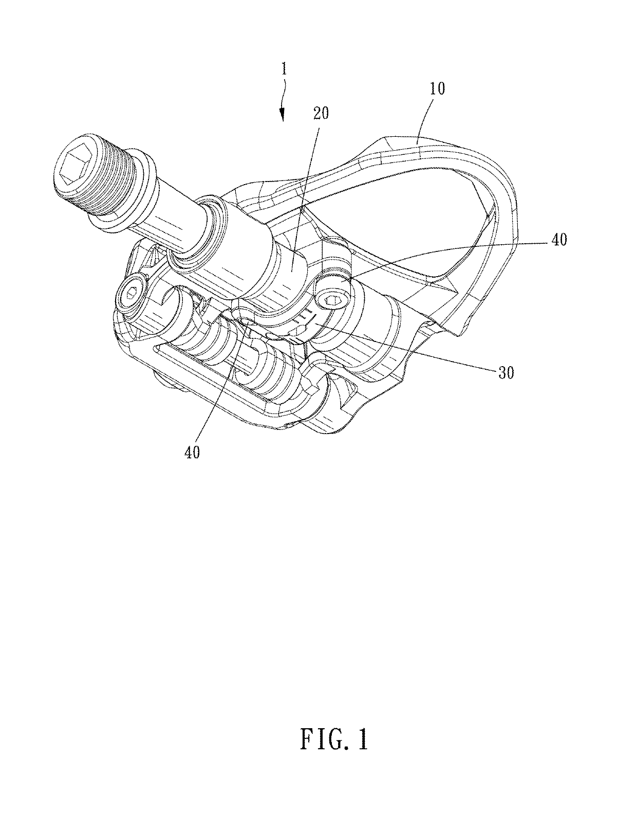
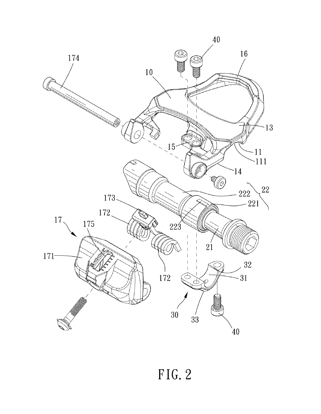
[0017]FIGS. 1 to 9 show an adjusted pedal according to a preferred embodiment of the present invention. The adjusted pedal 1 includes a pedal body 10, a pedal shaft 20 and an engaging portion 30.

[0018]The pedal body 10 has two clamp portions 16, 17 respectively configured to engage with a shoe. The pedal shaft 20 defines an axial direction, the pedal shaft 20 is configured to be assembled to a crank 2. The engaging portion 30 is disposed on the pedal body 10, and movably engaged with the pedal shaft 20 so that the pedal body 10 is slidable positionly to the pedal shaft 20 along the axial direction. The engaging portion 30 can be removably or unremovably connected with the pedal body 10. The engaging portion 30 and the pedal body 10 can be connected to each other through screw structures, male-female buckles, etc. Wherein when the engaging portion 30 is disengaged with the pedal shaft 20, no matter totally or partially release with respect to the pedal shaft 20, the pedal body 10 is ...


PUM


Abstract

An adjusted pedal is provided, including: a pedal body, having two clamp portions respectively configured to engage with a shoe; a pedal shaft, defining an axial direction; an engaging portion, disposed on the pedal body and movably engaged with the pedal shaft so that the pedal body is slidable positionly to the pedal shaft along the axial direction; wherein when the engaging portion is disengaged with the pedal shaft, the pedal body is slidable to the pedal shaft along the axial direction.

Description

BACKGROUND OF THE INVENTIONField of the Invention[0001]The present invention relates to an adjusted pedal.Description of the Prior Art[0002]A bicycle clipless pedal has a first clamp end and a second clamp end pivotably connected therewith so as to engage with a shoe cleat. Thus, foot portions of a rider can engage with the clipless pedal and avoid disengagement when riding. Compared with a pedal without a clamp structure, the clipless pedal has a high effort-saving and a high acceleration. Therefore, the clipless pedal is usually used in mountain bikes, cross-country bikes, race bikes, etc.[0003]Foot pedal positions and pedaling manners of users will affect the pedaling efficiency in general. Everyone feet are in different sizes, shapes, and everyone has the different foot pedaling manners. Moreover, a distance between the shoe cleat and a crank will affect an effort-saving. For example, the number of turns of the pedal per minute will increase when the shoe cleat is disposed close...

Claims


Application Information

Patent Timeline
IPC IPC(8): B62M3/08F16B17/00F16B9/02F16B2/02F16B7/04
CPCF16B2/02F16B7/04F16B9/02F16B17/00B62M3/086F16B2/065
Inventor CHEN, CHUNG-I
Owner CHEN CHUNG I
Why Eureka
Try Eureka