
Text input keyboard

a keyboard and text input technology, applied in the field of physical keyboards, can solve the problems of reducing the efficiency of input work, and achieve the effects of improving the total operability of the keyboard, facilitating and without looking keys, and improving usability of simultaneous key operation

Active Publication Date: 2019-04-30
KUBOTA MASASHI
View PDF58 Cites 1 Cited by
  • Summary
  • Abstract
  • Description
  • Claims
  • Application Information

AI Technical Summary

Benefits of technology

[0016]The key arrangement above, makes it possible to operate the five keys of the keyboard, two keys at the home position of thumbs, one key at the intermediate of them, and two keys at the outside of them, easily and without looking keys.
[0017]Because the one shift key and the one control key are placed on the position where can be operated by the thumbs with little influence to the positioning of other fingers, the usability of simultaneous key operation with the shift key or the control key and the other keys are improved.
[0018]Because the one shift key and the one control key are placed on the position where can be operated by the thumbs, it becomes possible to omit the shift keys and the control keys on the outside of the character keys. By placing the other function keys at these positions, for example the delete key or the escape key, the total operability of the keyboard is improved.
[0019]Because of the increase of the number of the key around the home positions of the thumbs, it is enable to assign the function keys such as the direction keys or the enter key, which are frequently used in the Japanese input application, MS-IME (Microsoft Corporation, registered trademark), Google Japanese input (Google Inc., registered trademark), ATOK (Just Systems Corporation, registered trademark) etc. These keys are now located too far from the home positions of the fingers as their importance. This change of the key arrangement improves the efficiency of the input work.
[0020]The placement of the shift key in the present invention, makes it easy to use the simultaneous key operation of the shift key and the character key, which is used only a little in the Japanese input work. Utilizing that improves the efficiency of the Japanese input work. (FIG. 3).
[0021]Because of the morphological feature “setting the independent keys on the home position of thumbs”, the present invention is suitable for the virtual thumb shift keyboards with so called the key remapper (An application to customize the key arrangement of the keyboard).

Problems solved by technology

As the result of the such arrangement, shift keys and control keys should be placed both on the right and left side, and it makes difficult to co-operate the shift key and the control key with the other key, causes a decrease in the efficiency of the input work.
That is, problem of efficiency reduction of the input work caused by such irrational key arrangement of the keyboard for a personal computer or the like.

Method used


Image

  • Text input keyboard
  • Text input keyboard
  • Text input keyboard

Examples


example 1

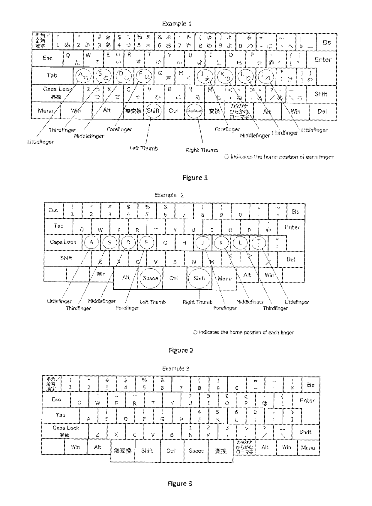
[0031]FIG. 1 is the example of the embodiment of the present invention in the Japanese keyboard for a personal computer. In this example, the shift key is placed on the home position of the left thumb, the space key is placed on the home position of the right thumb, and the control key is placed between them. In addition, two control keys generally to be placed in the outer edge of the character key column, and one shift key generally to be placed in the left outer edge of the character key column, are omitted. The key placed on the outside of the home position of the left thumb is Muhenkan key, and the key placed on the outside of the home position of the right thumb is Henkan key. The width of the three keys located in the home position of the left and right thumb and between them, are nearly 1 time of that of character key.

example 2

[0032]FIG. 2 is the example of the embodiment of the present invention in the English keyboard for a personal computer. In this example, the shift key is placed on the home position of the right thumb, the space key is placed on the home position of the left thumb, and the control key is placed between them. In addition, two control keys generally to be placed in the outer edge of the character key column, and one shift key generally to be placed in the right outer edge of the character key column, are omitted. The key placed on the outside of the home position of the left thumb is Alt key, and the key placed on the outside of the home position of the right thumb is Menu key. The width of three keys located in the home positions of the left and right thumbs and between them, are nearly 1.3 times of that of character key.

example 3

[0033]FIG. 3 is the example of the embodiment of the present invention in the Japanese keyboard for a personal computer. In this example, the key remapper, the application to customize the key arrangement of the keyboard which is provided for a fee or free of charge over the Internet, is applied to improve the efficiency of Japanese input work. The letter or the symbol input by the single typing of the key is illustrated in the center of the top of each key, and the characters or symbols input by the simultaneous keystrokes with the shift key are illustrated in the lower part of the key. In Japanese input work, when using Roman characters with the the common QWERTY layout, the operator is forced to do difficult key operation, because it is essential to use the uppermost line of the character key column, in order to input number, dash or bracket. In this example, by using the key remapper, numbers, dash and bracket and the like are designed to be input by the simultaneous keystrokes ...


PUM


Abstract

The character input keyboard. One shift key and one space key are placed on the home position of the left and right thumb, and one control key is placed between them. These keys have the width from 1 to 1.5 times of the character key.

Description

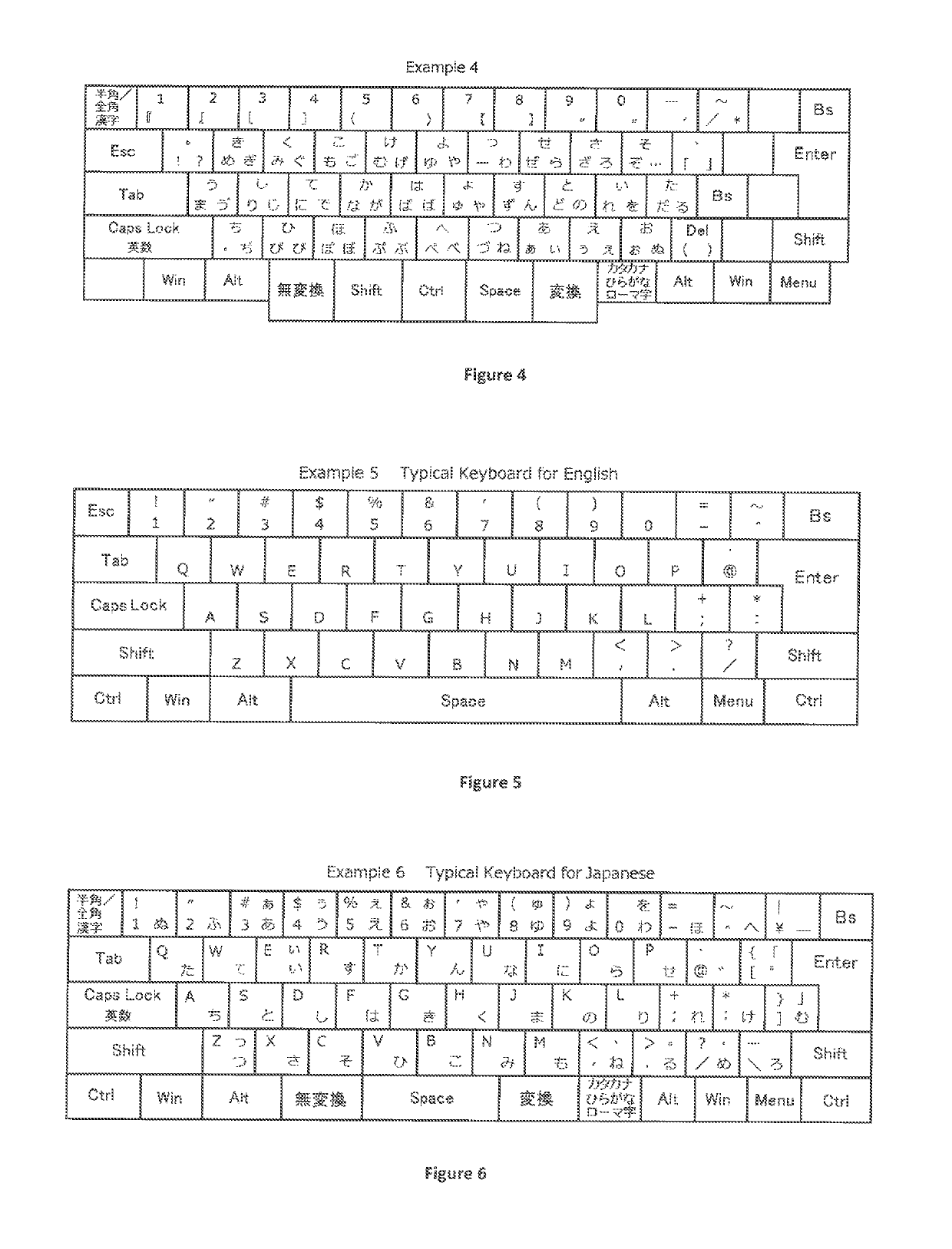
TECHNICAL FIELD[0001]The present invention concerns a physical keyboard for a word processor or a personal computer or the like, and concerns a software keyboard on the touch panel screen of a tablet computer, which is used to input characters.TECHNICAL BACKGROUND[0002]The personal computer keyboard commonly used in the English-speaking area, is consisting of five rows of character keys, and at the center of the bottom row, there is a large space key which have several times width of a general character key. Shift keys and control keys are placed on the outer edges of the character key column, and designed to be co-operated with the little finger of the opposite side to the hand which stretch the character key (FIG. 5). Such key arrangement is taken over from the design of the mechanical typewriter which was dominant in the 19th century.[0003]Also in the JIS (Japanese Industrial Standards) keyboard for input Japanese, the space key is placed in the bottom center of the character key...

Claims


Application Information

Patent Timeline
Patent Type & Authority Patents(United States)
IPC IPC(8): G06F3/02H03M11/14G06F3/01G06F3/0488G06F3/023H03M11/06G06F3/048G06F3/0489
CPCG06F3/0216G06F3/018G06F3/023H03M11/14G06F3/0233G06F3/04886H03M11/06G06F3/0219
Inventor KUBOTA, MASASHI
Owner KUBOTA MASASHI
Learn More