
Suction/compression assembly for a waste material aspiration system

a vacuum system and waste material technology, applied in the direction of check valves, multiple way valves, functional valve types, etc., can solve the problems of reducing the life, reducing the life, and being totally ineffective for vacuum system sealing, so as to increase the life of the valve itsel

Active Publication Date: 2019-05-07
JUROP
View PDF10 Cites 0 Cited by
  • Summary
  • Abstract
  • Description
  • Claims
  • Application Information

AI Technical Summary

Benefits of technology

[0018]The assembly according to the invention further comprises a one-way valve arranged within the intake pipe in a position adjacent to the third opening of the seat of the four-way valve. It has been observed that the new position assigned to the one-way valve allows to obtain the seal in any operative condition of the system while increasing the life of the valve itself. At the same time, the intake / compression assembly is obtained by assembling a markedly reduced number of components for the benefit of manufacturing and maintenance costs.

Problems solved by technology

It was observed that in suction / compression assemblies, whether they are provided or not with a cooling air injection system, the one-way valve is a critical issue particularly in terms of maintenance costs.
The ball, made of polymeric material, which constitutes the one-way valve is impinged by air / gas at high temperature that markedly reduce the life thereof.
It was also observed that when the assembly is provided with a cooling air injection system, a directional valve arranged in the exhaust pipe is only effective for the sealing of a pressurized system, but totally ineffective for the sealing of a vacuum system.
The use of pneumatic valves, however, has a considerable impact on the implementation costs and subsequently on those related to maintenance.

Method used


Image

  • Suction/compression assembly for a waste material aspiration system
  • Suction/compression assembly for a waste material aspiration system
  • Suction/compression assembly for a waste material aspiration system

Examples


Embodiment Construction

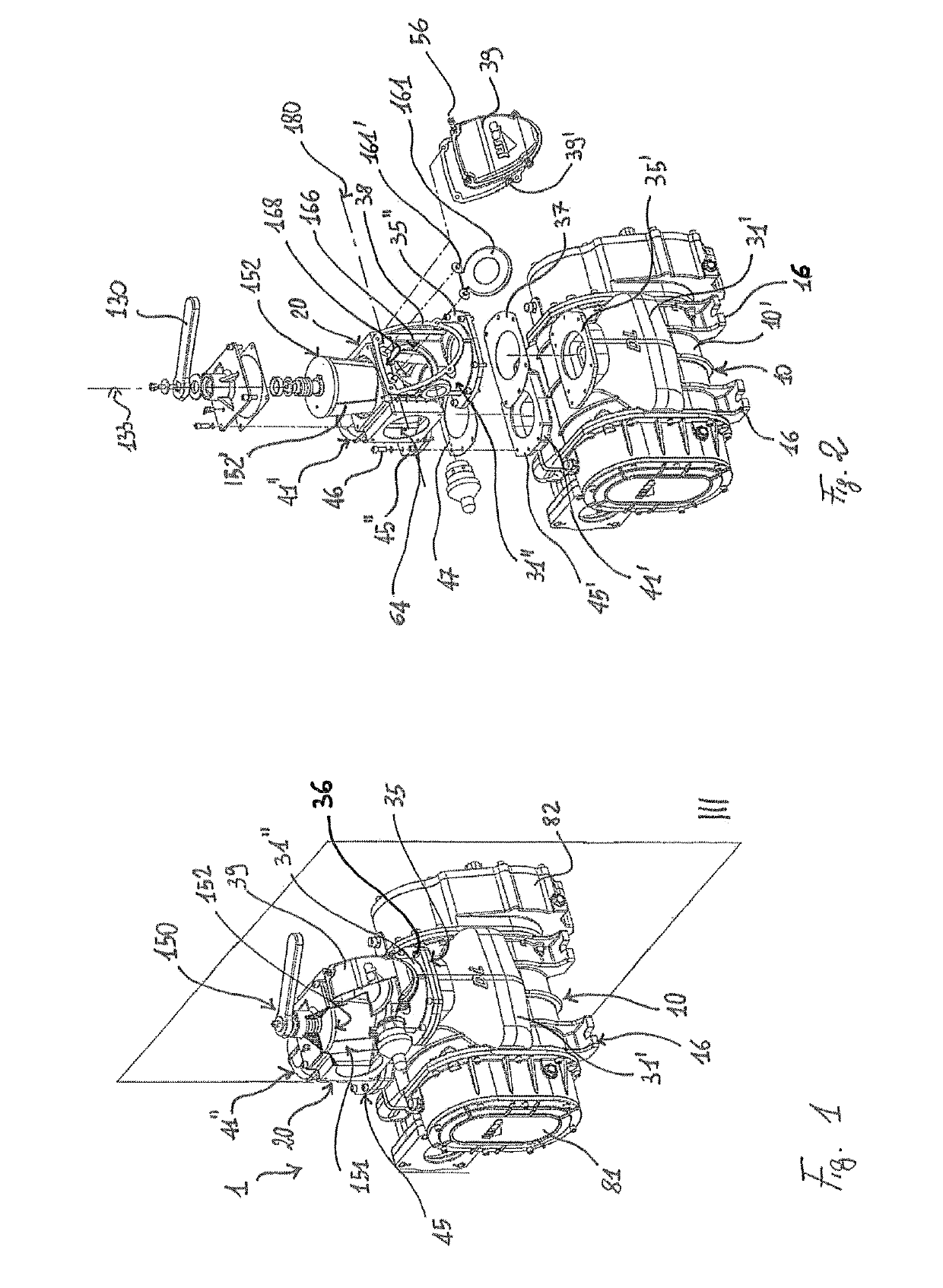
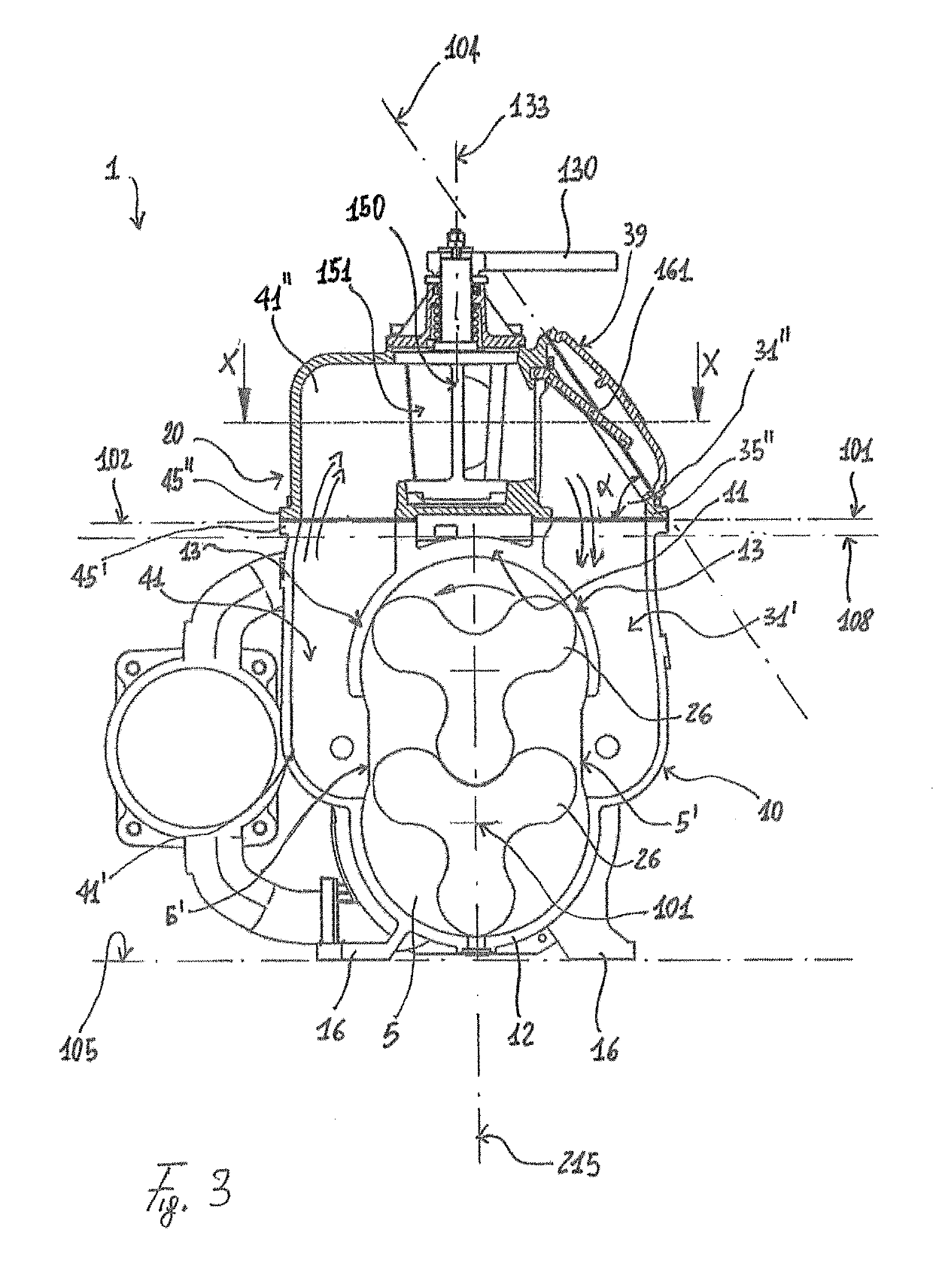
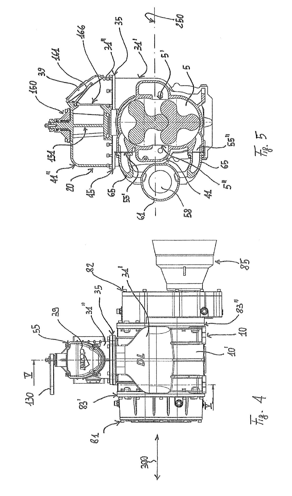
[0029]With reference to the above figures, the suction / compression assembly according to the invention is generically indicated with reference numeral 1. Such an assembly 1 can be used to aspirate gases (such as air) from a system 100, or alternatively to introduce air under pressure (compressed) within the system itself.

[0030]Assembly 1 comprises an operating machine, which includes a chamber 5 (shown in FIG. 3) inside of which operative means are housed, configured to transfer gas from an intake section 5′ to an exhaust section 5″ both defined by the chamber itself. In a first possible embodiment, the operating machine can be of volumetric type, that is, configured to transfer gases from the intake section 5′ to the exhaust section 5″ without compressing the gas itself. To this end, with reference to FIG. 3, the operative means may comprise a pair of lobe rotors 26 having parallel axes. In an alternative embodiment, chamber 20 and the operative means 25 may be configured so as to ...


PUM


Abstract

The invention relates to a suction / compression assembly for aspirating / compressing gases from / in a system to / from an external environment. The assembly comprises an operating machine, a four-way valve, an intake pipe and an exhaust pipe connecting an intake section and an exhaust section of the operating machine to said four-way valve, respectively. The assembly is characterized in that it comprises a first body, which defines, in one piece, a chamber of the operating machine, a first portion of the intake pipe and a first portion of said exhaust pipe. The assembly further comprises a second body, which defines, in one piece, a seat of the four-way valve, a second portion of the intake pipe and a second portion of the exhaust pipe. Moreover, the assembly according to the invention comprises a one-way valve arranged within the intake pipe in a position adjacent to the seat of the four-way valve.

Description

CROSS-REFERENCE TO RELATED APPLICATIONS[0001]The present application claims priority to Italian Patent Application No. 102015000024766 filed Jun. 17, 2015, the entirety of the disclosures of which are expressly incorporated herein by reference.STATEMENT RE: FEDERALLY SPONSORED RESEARCH / DEVELOPMENT[0002]Not ApplicableFIELD OF THE INVENTION[0003]The present invention falls within the scope of the manufacture of equipment and / or systems for aspirating waste material in liquid, solid, sludge form, etc. In particular, the invention relates to a suction / compression assembly connectable to a system operating in vacuum and / or under pressure.BACKGROUND ART[0004]In the manufacture of equipment for cleaning and / or the collection and treatment of waste it is known to use intake / compression assemblies configured to generate the vacuum in a collection system, which may be for example a cistern, and / or to compress air in the system itself. More specifically the term “intake / compression assembly” m...

Claims


Application Information

Patent Timeline
Patent Type & Authority Patents(United States)
IPC IPC(8): F04C29/12F01C21/10F16K15/03F16K11/08F04C18/12F04C18/08
CPCF04C29/124F01C21/10F04C18/086F16K11/08F16K15/03F04C18/126F04C2240/806F04C2240/30
Inventor SANTAROSSA, DANILO
Owner JUROP
Learn More