
High cycle and speed valve

Active Publication Date: 2016-07-14
PARKER INTANGIBLES LLC
View PDF0 Cites 0 Cited by
  • Summary
  • Abstract
  • Description
  • Claims
  • Application Information

AI Technical Summary

Benefits of technology

The present invention is an improved high cycle and speed valve that reduces valve failure modes caused by wear and friction. The valve has a non-wearing valve seat with a lower static section and an upper dynamic section. The lower static section performs a seat retention function, while the upper dynamic section has sufficient clearance between the valve seat and valve body to prevent significant contact during sealing. This results in increased valve life and reliability, and a higher mean-time-to-failure (MTTF) compared to conventional configurations.

Problems solved by technology

Such rapid response time and related high cycling renders manual valves impractical, and pneumatically actuated valves are therefore preferred.
Given the high cycling of HCS valves, however, such as in ALD processes, even a one million cycle MTTF significantly constrains the useful life of such valves.
The need for frequent valve replacement or repair remains a substantial performance issue for HCS valves, particularly in ALD and comparable processes.
One source of potential HCS valve failure is valve seat wear.
It is known, however, that in actuality there indeed tends to be slight movement and displacement of the valve seat relative to the adjacent valve components that house the valve seat.
In particular, high gas pressure from the inlet side of the valve tends to move the valve seat out of position.
Such repeated displacement is sufficient to damage the valve over time, for as the valve seat moves against adjacent valve components, the friction causes valve seat wear to occur.
The valve seat wear results in leakage space being present even when the valve is closed, which permits external leakage of the fluids flowing through the valve.
With the high cycling of HCS valves, even the slight movement of the valve seat accumulates significant valve seat wear that diminishes the valve life.
Another source of potential HCS valve failure is fatigue failure of the diaphragm that results in the valve being unable to close fully.
This also can result is external leakage of the fluids flowing through the valve.
The rubbing of the metal diaphragm against adjacent metal components (e.g., against the valve cap or again another stainless steel diaphragm in a multi-diaphragm configuration) leads to damaging wear of the diaphragm.
The fretting also may occur unevenly across the diaphragm, and where the fretting is concentrated cracks can occur in the diaphragm.
In view of both valve seat wear and diaphragm fretting, the reliability and valve life, as measured for example by the MTTF, has proven to be deficient for high cycling applications.

Method used


Image

  • High cycle and speed valve
  • High cycle and speed valve
  • High cycle and speed valve

Examples


Embodiment Construction

[0019]Embodiments of the present invention will now be described with reference to the drawings, wherein like reference numerals are used to refer to like elements throughout. It will be understood that the figures are not necessarily to scale.

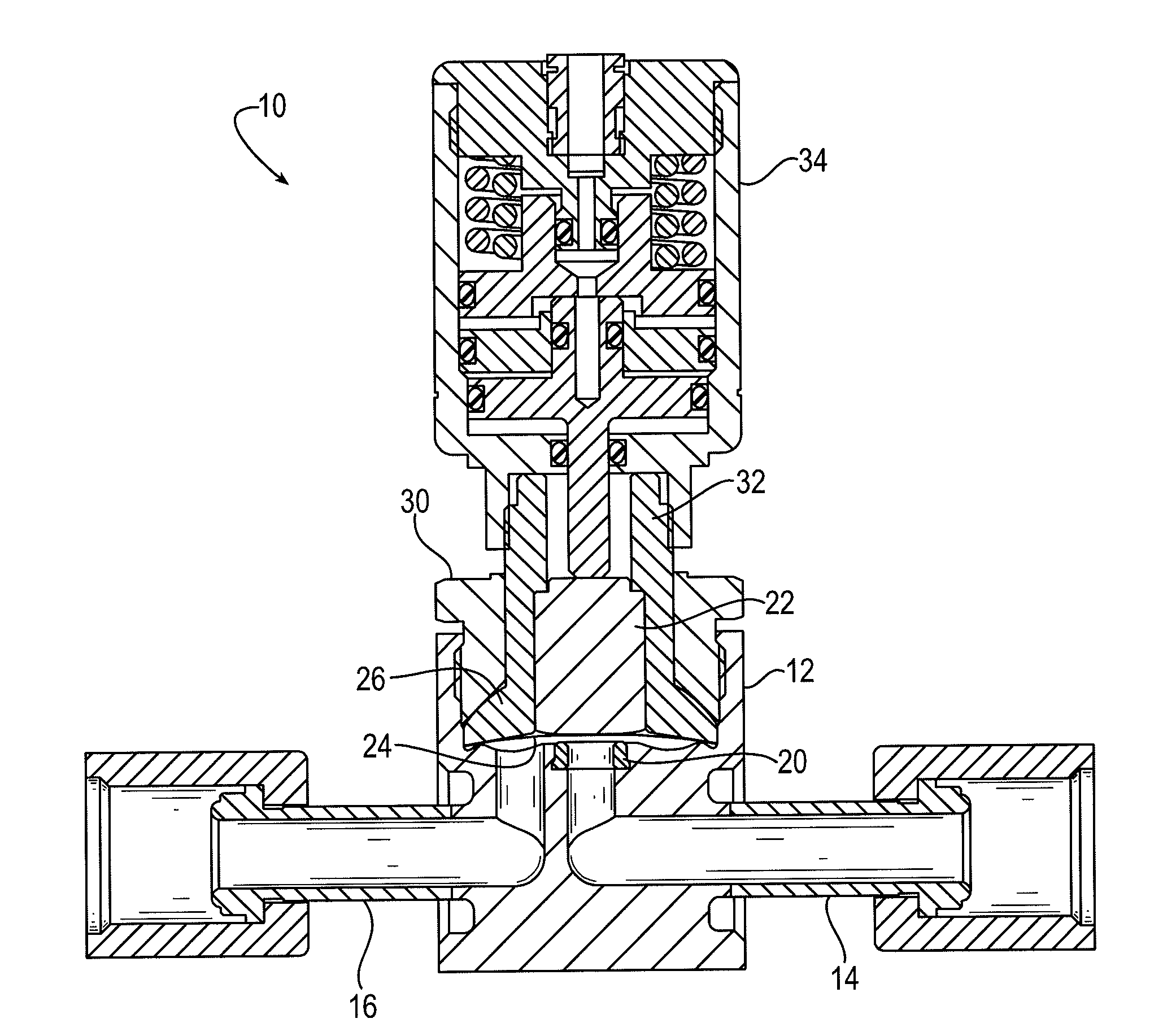
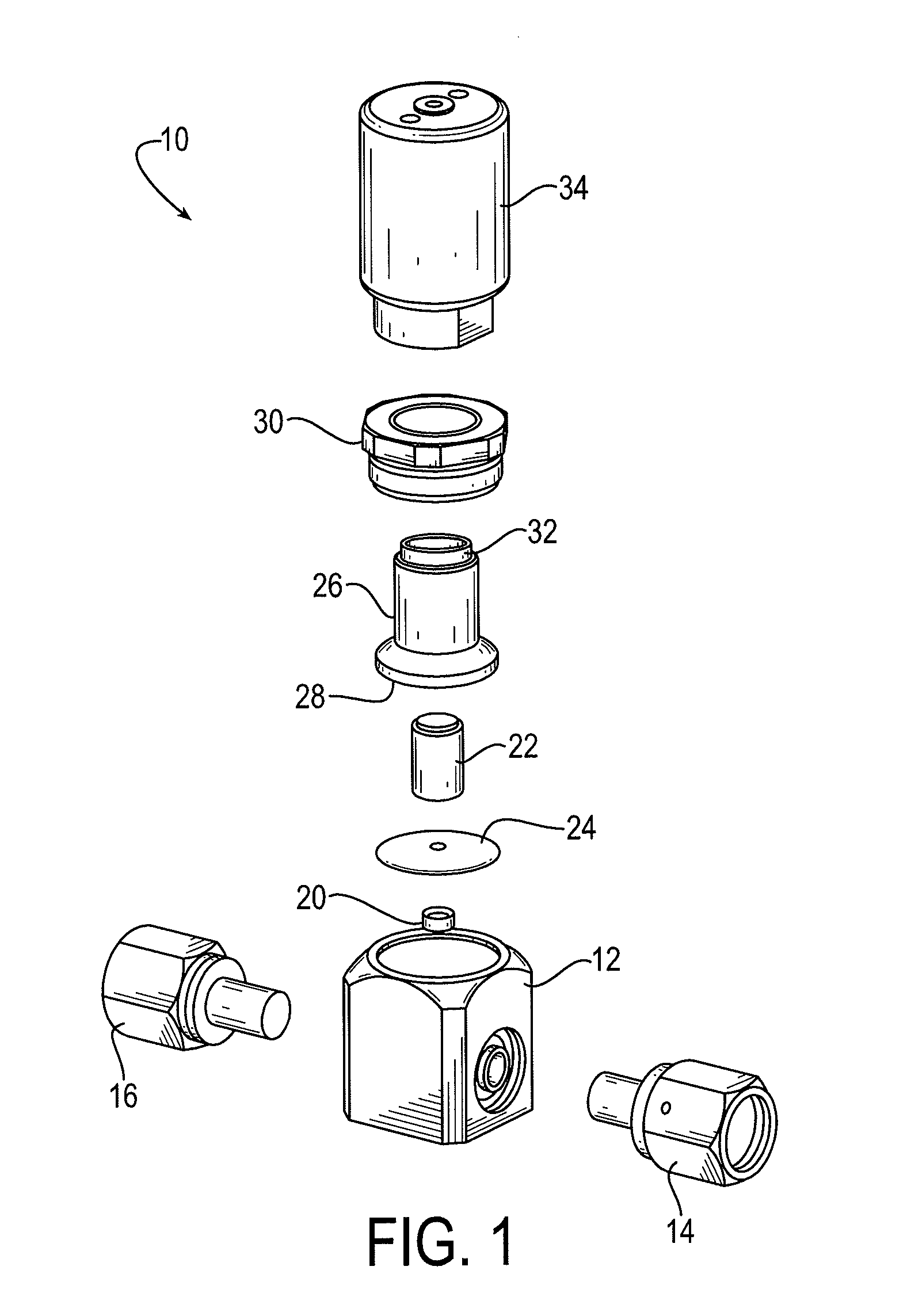
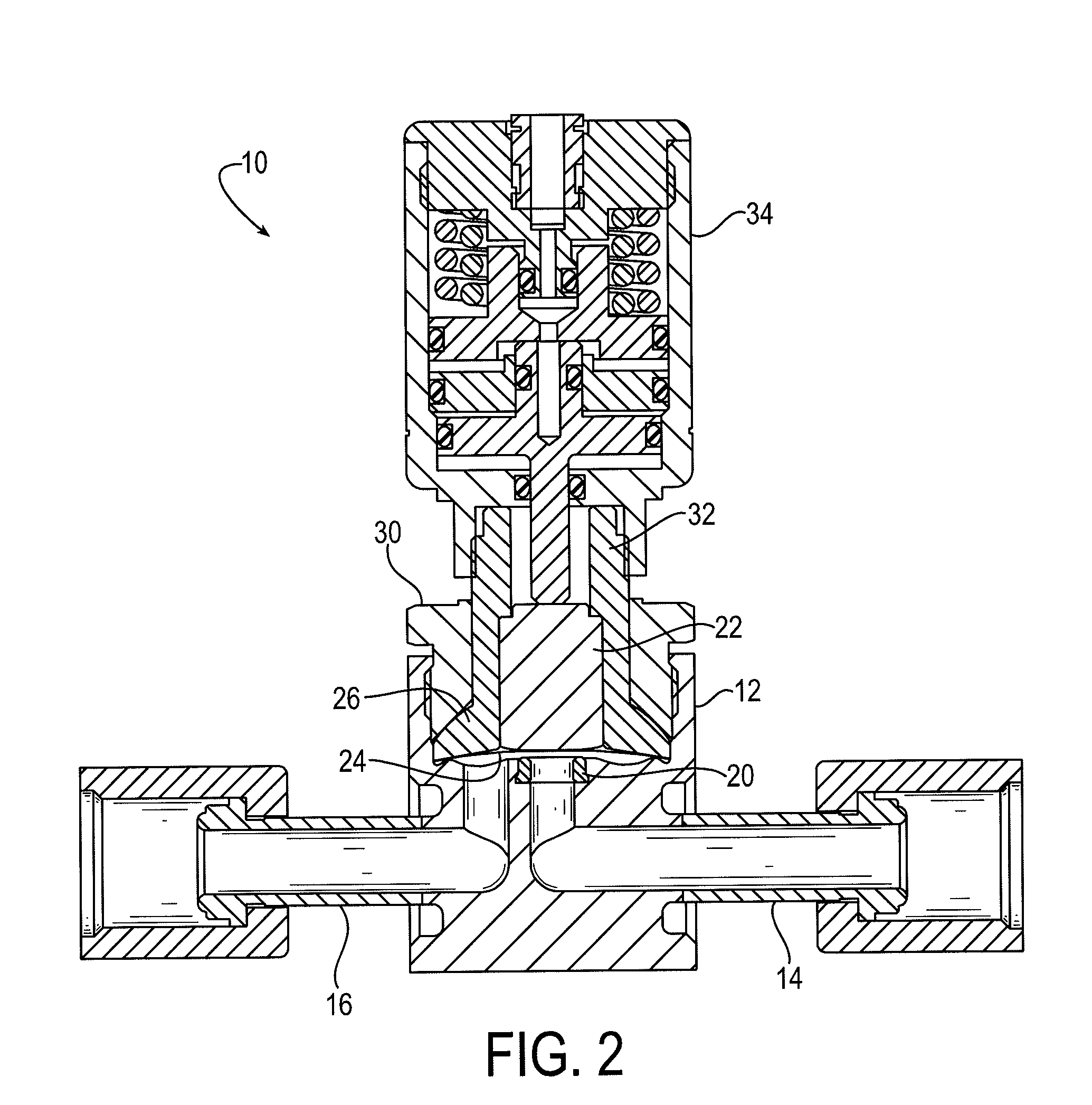
[0020]FIG. 1 is a schematic diagram that depicts an exploded isometric view of an exemplary high cycle and speed (HCS) valve 10 in accordance with embodiments of the present invention. FIG. 2 is a schematic diagram that depicts a side cross-sectional view of an exemplary HCS valve 10 comparable to the HCS valve depicted in FIG. 1. Like components are therefore identified by common reference numerals in FIGS. 1 and 2.

[0021]The HCS valve 10 includes a body 12 that acts as a housing to secure the other valve components. Fluid interfaces 14 and 16 respectively provide a fluid inlet and outlet for fluids that may pass through the valve 10. The fluid interfaces 14 and 16 may include any suitable glands, fittings, and comparable components for attach...


PUM


Abstract

A high cycle and speed valve (10) includes a body (12), a valve seat (20) fixed within the body, and a diaphragm (24) that moves between a closed position in which the diaphragm is forced against the valve seat, and an open position in which the diaphragm is released from the valve seat. The valve seat includes a static section (40) that is secured within the body, and a dynamic section (42) that is compressed by the diaphragm when the diaphragm is in the closed position. The static section includes a radially extending flange (44) that is received in a recess (46) formed in the body to secure the static section in the body. The valve includes a body cavity relief space (52) into which the dynamic section compresses in the closed position. The valve further includes a cap (26) that has a dry film lubricant layer (58) that serves as a dry lubricant between the cap and the diaphragm.

Description

FIELD OF THE INVENTION[0001]The present invention is directed to high cycle and speed (HCS) valves, and particularly HCS valves including a pneumatically operated diaphragm that is actuated for high cycle rates for relatively low pressure operations.BACKGROUND OF THE INVENTION[0002]The High Cycle and Speed (HCS) valve is a pneumatically operated diaphragm valve for the Ultra High Purity (UHP) market. UHP valves are used, for example, in the manufacture of semiconductors in a process known as Atomic Layer Deposition (ALD). The gases used in ALD processes need to be free of impurities, which would compromise the function of the resultant semiconductors. ALD valves are required to open and close rapidly with a closing force of around 70 pounds of pressure. Pneumatic actuators generally are used to operate these valves because a pneumatic actuator can provide the requisite large closing force in a compact package, while being free of the kind of flammability risks associated with electr...

Claims


Application Information

Patent Timeline
IPC IPC(8): F16K25/04F16K7/14F16K25/00F16K31/12
CPCF16K25/04F16K25/005F16K7/14F16K31/12F16K7/16F16K7/17
Inventor MORGAN, DANIEL P.AUSTIN, THOMAS A.
Owner PARKER INTANGIBLES LLC
Learn More