Optimal partial reconfiguration of spectrum in optical networks

a spectrum reconfiguration and optical network technology, applied in the field of optical network systems and methods, can solve the problems of large unbounded implementation costs and the limitation of most conventional rwa and rsa algorithms, and achieve the effect of providing solutions for a small to medium network siz

Active Publication Date: 2019-05-21
CIENA
View PDF11 Cites 10 Cited by
  • Summary
  • Abstract
  • Description
  • Claims
  • Application Information

AI Technical Summary

Benefits of technology

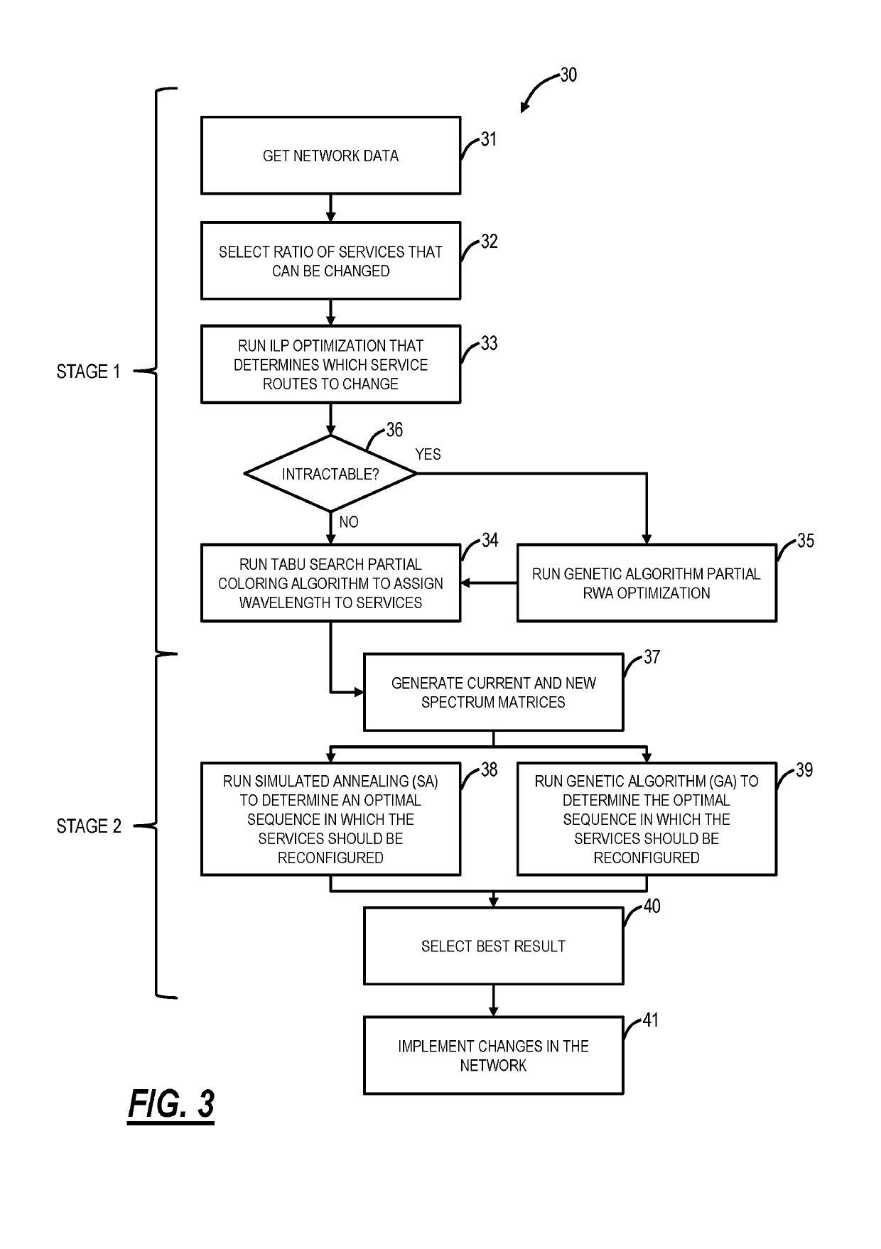
[0007]In another embodiment, a server configured to perform a partial optimization of wavelengths or spectrum in an optical network includes a processor; and memory storing instructions that, when executed, cause the processor to, based on current services in the optical network each having a route and wavelength assignment and based on a proportion of services that can be changed in the partial optimization, perform a first stage optimization to determine which of the current services are changed for one or more of the route and the wavelength assignment to attain a measurable advantage, perform a second stage optimization to determine an order of implementing changes from the first stage optimization that with the order minimizing one or more of conflicts and step counts, and cause implementation of the changes in the optical network based on the order to affect the measurable advantage. The memory storing instructions that, when executed, can further cause the processor to perform a plurality of the first stage optimization and the second stage optimization with different values of the ratio of services, and provide an output of the different values of the ratio of services and corresponding wavelength reduction and step count.

Problems solved by technology

The main shortcomings of the conventional approach are that the wavelength count will not be reduced as much as it could be for a given ratio of p-SNCs that are reconfigured, and the cost of implementation is largely unbounded.
Furthermore, most conventional RWA and RSA algorithms can only provide solutions for a small to medium network size (e.g., less than 50-100 nodes).

Method used


Image

  • Optimal partial reconfiguration of spectrum in optical networks
  • Optimal partial reconfiguration of spectrum in optical networks
  • Optimal partial reconfiguration of spectrum in optical networks

Examples


operational examples

[0077]The partial optimization process 30 was implemented on four example networks, referred to as networks 1, 2, 3, 4. These networks have the following characteristics in Table 4.

[0078]

TABLE 4Network topologies.# nodes# Total # ofWavelength Name(ROADM)linksp-SNCsCountTopologyNetwork 11420 9124InterconnectedmeshNetwork 2213821035InterconnectedmeshNetwork 3244727654InterconnectedmeshNetwork 4543 437 70252Interconnectedmesh

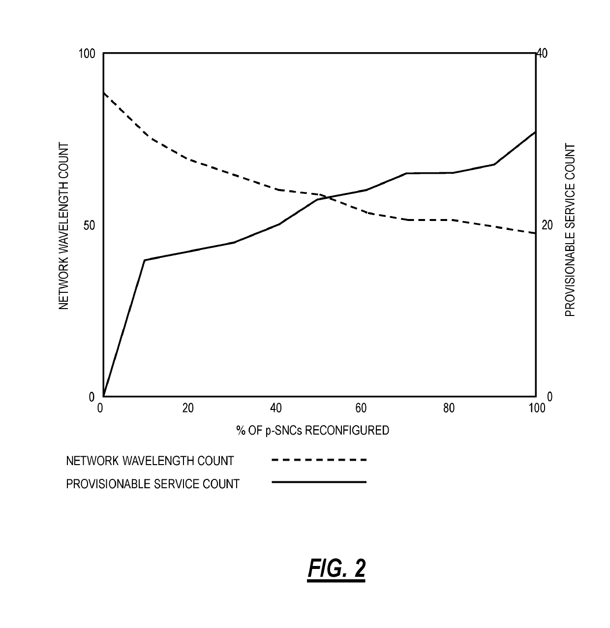
[0079]Table 5 shows the results of the first stage of the partial optimization process 30, which for each considered p-SNC ratio, shows the minimum wavelength count that can be attained across all the p-SNCs of the network (table 4). For each network, the performance of the ILP-TS algorithm and GA-TS approach is provided. A p-SNC ratio of 0% corresponds to the current state of the network, while a p-SNC ratio of 100% is equivalent to reconfiguring all p-SNCs.

[0080]For the networks 1, 2, 3, the GA-TS approach is either as good or better than the ILP-TS approach, as ...


PUM


Abstract

Partial optimization systems and methods of wavelengths or spectrum in an optical network include, based on current services in the optical network each having a route and wavelength assignment and based on a ratio of services that can be changed in the partial optimization, preforming a first stage optimization to determine which of the current services are changed for one or more of the route and the wavelength assignment to attain a reduction of a number of wavelengths; performing a second stage optimization to determine an order of implementing changes from the first stage optimization that with the order minimizing one or more of conflicts and step counts; and causing implementation of the changes in the optical network.

Description

FIELD OF THE DISCLOSURE[0001]The present disclosure generally relates to optical networking systems and methods. More particularly, the present disclosure relates to systems and methods for the optimal partial reconfiguration of spectrum / wavelengths in optical networks such as Dense Wavelength Division Multiplexing (DWDM) networks.BACKGROUND OF THE DISCLOSURE[0002]Routing and Wavelength Assignment (RWA) is a well-known problem for fixed grid optical networks while Routing and Spectrum Assignment (RSA) is its equivalent term to the same problem for flexible grid optical networks. In fixed grid optical networks, wavelengths are spaced apart from each other according to a wavelength spectrum grid defined by International Telecommunication Union (ITU) in ITU-T G.694.1 (02 / 12), “Spectral grids for WDM applications: DWDM frequency grid,” the contents of which are incorporated by reference. In flexible grid optical networks, which is also described in ITU Recommendation G.694.1 “Spectral g...

Claims


Application Information

Patent Timeline
Patent Type & Authority Patents(United States)
IPC IPC(8): H04J14/02H04B10/077H04B10/508
CPCH04J14/0227H04J14/0267H04J14/0241
Inventor CHATELAIN, BENO TBRUECKHEIMER, SIMONSTACEY, DAVIDMAAMOUN, KHALED
Owner CIENA
Why Eureka
Try Eureka