Closure assembly for a medical connector

a technology for closing caps and connectors, which is applied in the direction of tube connectors, intravenous devices, other medical devices, etc., can solve the problems that the addition of female connectors may remain unused, and achieve the effects of facilitating the passage of the female connector, facilitating the free rotation of the closure cap, and facilitating the unthreading or twisting off of the medical connector

Active Publication Date: 2019-05-28
INT MEDICAL INDS
View PDF267 Cites 20 Cited by
  • Summary
  • Abstract
  • Description
  • Claims
  • Application Information

AI Technical Summary

Benefits of technology

[0014]Additional structural and operative features of the closure assembly include a housing assembly. In at least one embodiment, the housing assembly comprises a closure sleeve having an access opening formed at one end thereof. The closure sleeve and the access opening are cooperatively dimensioned with the exterior of the closure cap to facilitate its passage into the interior of the closure sleeve. Moreover, when initially in the open orientation and with the medical connector being attached thereto, the closure cap may be forced into the access opening and pass into the interior of the closure sleeve. In doing so, the cooperative dimensioning of the access opening will allow passage of the closure cap there through but concurrently force the one or more segments from the open orientation into the closed orientation. As set forth above, when in the closed orientation the interior surfaces of the one or more segments will be forced into mating engagement with exterior portions or surfaces of the medical connector. It is further noted that in at least one embodiment, once disposed on the interior of the closure sleeve, the closure cap and the medical connector attached thereto, may freely rotate within the closure cap in opposite directions.
[0015]Yet additional structural features of one or more embodiments of the closure assembly include the provision of a retention structure formed on interior portions of the closure sleeve. Such a retention structure includes an inwardly protruding wall portion which may be disposed in interruptive, abutting relation to an exterior portion of the closure cap. Therefore, any attempt to remove the medical connector and attached closure cap, such as by exerting an outwardly directed pulling force thereon, will result in abutting, retaining engagement of the retention structure on the interior of the closure cap and the corresponding protruding portion on the exterior surface of the closure cap. This abutting interaction will prevent the closure cap and the attached medical connector from being “pulled” from the interior of the closure sleeve.
[0016]In addition, due to the free rotation of the closure cap within the interior of the closure sleeve, the medical connector will normally not be able to be “unthreaded” or rotated relative to the closure cap. Therefore, removal of the medical connector from the

Problems solved by technology

However, such an additional female connector may remain unused or may be accessed subsequently to the initiation o

Method used


Image

  • Closure assembly for a medical connector
  • Closure assembly for a medical connector
  • Closure assembly for a medical connector

Examples


Embodiment Construction

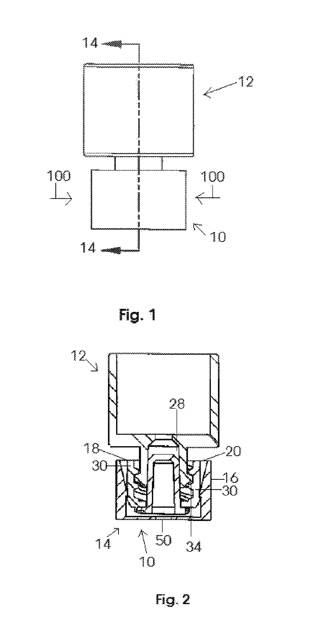
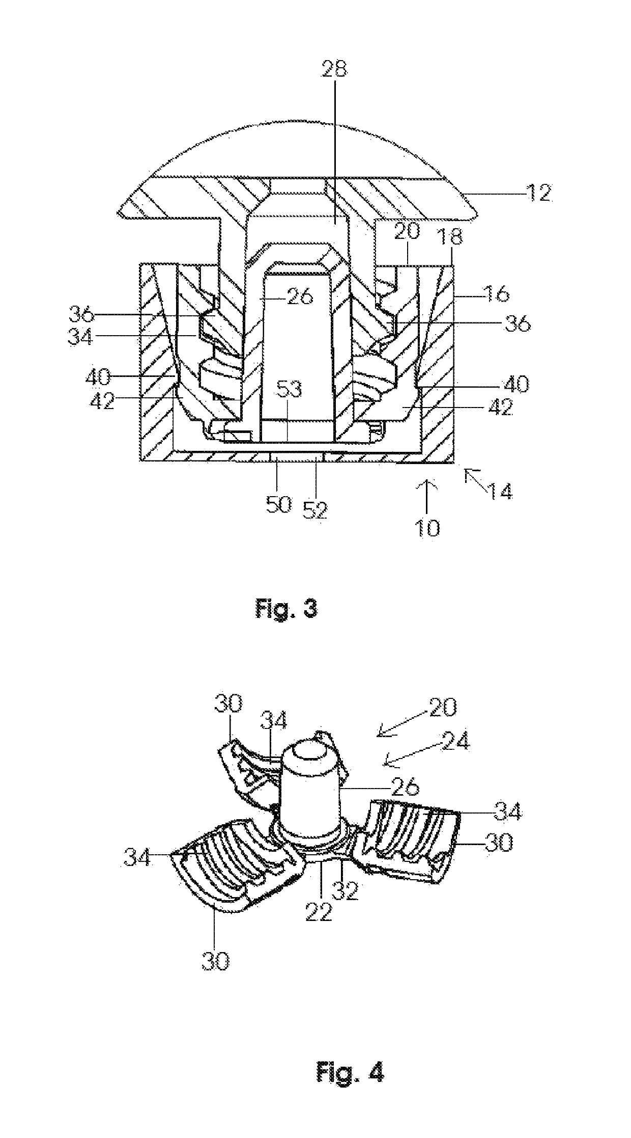
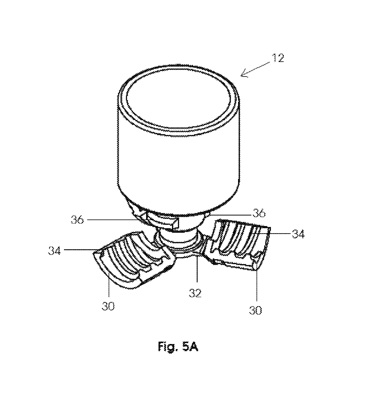
[0032]As represented in the accompanying Figures, the present invention is directed to a closure assembly, generally indicated throughout the Figures as 10, which is structured for flow restricting relation, and in some cases flow stopping relation, to a medical connector, generally indicated as 12. By way of example only, the “medical connector”12 to which the closure assembly 10 may be attached may include, but not be limited to, a lure connector, Enteral connector, Neuraxial connector, as well as other connector type structures including a needleless syringe, IV assembly, medical tubing, etc., commonly utilized in the medical and related arts. Moreover, one or more preferred embodiments of the closure assembly 10 may be operative in a “push-on, twist-off” mode for respective attachment to and removal from a female type medical connector 12, as will also be explained in greater detail hereinafter.

[0033]With initial reference to FIGS. 2 and 3, the closure assembly 10 also includes ...


PUM


Abstract

A closure assembly structured to be attached in flow restricting relation to a medical connector and removed therefrom utilizing a push-on and twist-off manipulation. The closure assembly comprises a cap having a preferably male flow restricting portion, wherein the cap is operatively disposed in removable, flow restricting attachment to a female medical connector. A plurality of segments collectively define a sidewall of the cap and are individually and collectively movable between an open orientation and a closed orientation relative to at least the flow restricting portion and a medical connector attached thereto. The closed orientation comprises the plurality of segments disposed in covering, retaining relation to the attached medical connector and the open orientation comprises an outward disposition of the plurality of segments and an accessible, exposure of the flow restricting portion. A tamper evident structure may be operatively associated with a housing assembly of the closure assembly.

Description

CLAIM OF PRIORITY[0001]The present application is based on and a claim of priority is made under 35 U.S.C. Section 119(e) to a provisional patent application that is in the U.S. Patent and Trademark Office, namely, that having Ser. No. 62 / 126,154 and a filing date of Feb. 27, 2015 and which is incorporated herein by reference.BACKGROUND OF THE INVENTIONField of the Invention[0002]This invention is directed to a closure assembly, which may be operative in a “push-on, twist-off” mode, and which is structured to be attached in flow-restricting relation to a medical connector. The invention includes a closure cap having a flow-restricting portion and a sidewall defined by a plurality of segments positionable between open and closed orientations, relative to the flow-restricting portion and the medical connector attached thereto. A housing assembly may be disposed in enclosing, retaining relation to the closure cap and may include a tamper evident structure.Description of the Related Art...

Claims


Application Information

Patent Timeline
IPC IPC(8): A61M39/10A61M39/20
CPCA61M39/20A61M39/1011A61M5/5086
Inventor HUNT, TIMOTHY BRANDON
Owner INT MEDICAL INDS
Why Eureka
Try Eureka