
Lamp

a technology of lamp and socket, which is applied in the direction of lighting support devices, coupling device connections, lighting and heating apparatus, etc., can solve the problems of bulky usb connectors, affecting the overall esthetics of the standard, and affecting the installation of usb connectors in the standard lamp. , to achieve the effect of reducing the space volume required for installation, reducing the size of the usb interface, and increasing the flexibility of installing the usb interfa

Active Publication Date: 2019-05-28
CHEN CHING HUI
View PDF10 Cites 1 Cited by
  • Summary
  • Abstract
  • Description
  • Claims
  • Application Information

AI Technical Summary

Benefits of technology

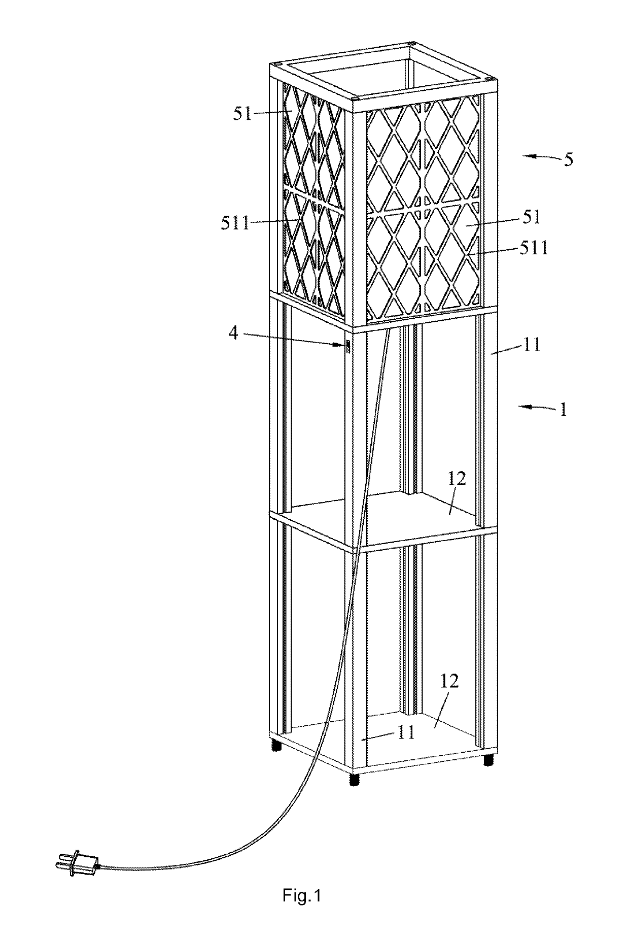
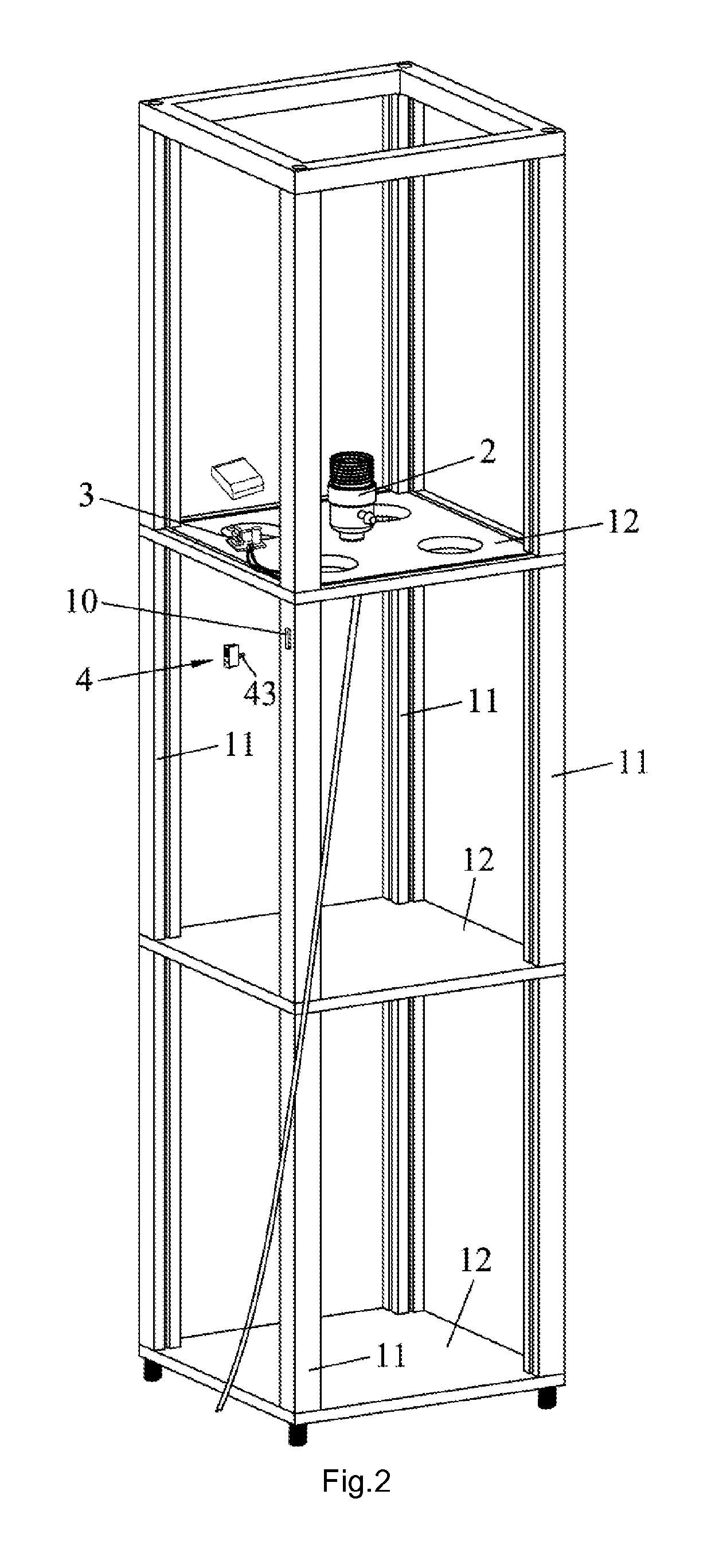
[0005]The primary objective of the present invention is to provide a lamp to improve the convenience of installing the USB interfaces and the overall esthetics of the base.
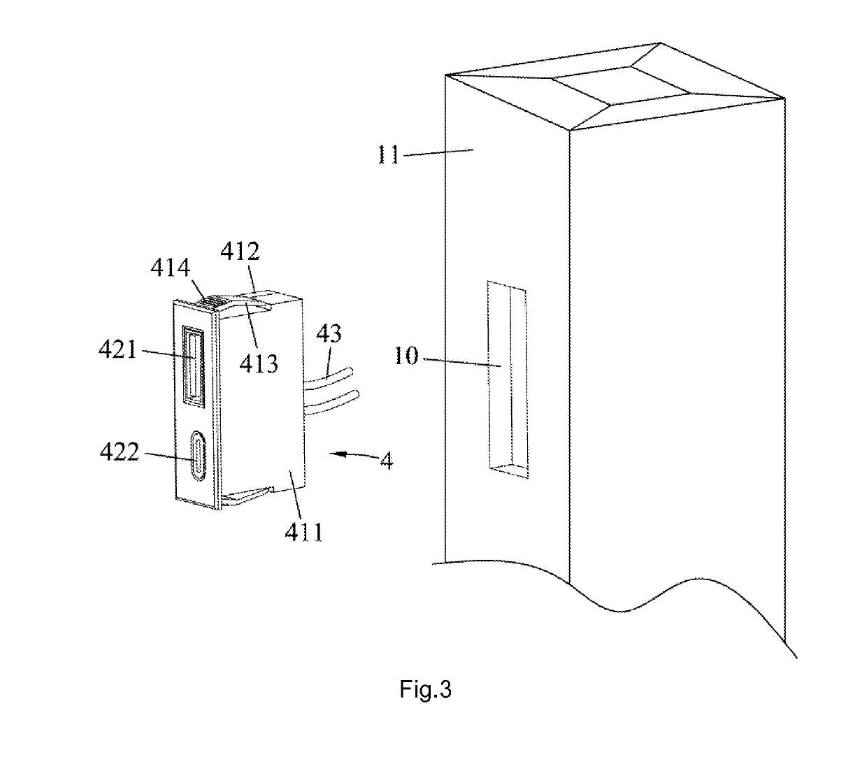
[0007]The present invention respectively disposes the USB socket module and the circuit board at different positions, whereby to reduce the size of the USB interface and decrease the space volume required for installing the USB interface. Therefore, the present invention can increase the flexibility of installing the USB interface (e.g. installing the USB interface in a smaller base) and improve the overall esthetics of the base.

Problems solved by technology

However, such a structure containing the USB connectors and the circuit board occupies a larger volume and may hinder the installation of the USB connectors.
For example, it is inconvenient to install the UBS connectors in the standard of the standard lamp, especially a smaller standard.
Further, the bulky USB connectors are likely to degrade the overall esthetics of the standard.

Method used


Image

  • Lamp
  • Lamp
  • Lamp

Examples


Embodiment Construction

[0012]Below, embodiments and attached drawings are described in detail to clearly and completely demonstrate the technical contents of the present invention. It should be noted: these embodiments are not all the embodiments but only a part of the embodiments of the present invention; the embodiments made by the persons having ordinary knowledge in the field according to the technical contents of the present invention without creative labor would be included by the scope of the present invention.

[0013]It should be noted also: the positional or directional adjective used in the specification, such as upper, lower, left, right, front, rear, top, bottom, inner, outer, vertical, horizontal, transverse, longitudinal, clockwise, counterclockwise, circumferential, radial, axial, etc., is only to describe the relative position of the components in a special viewing angle. If the viewing angle is changed, the positional or directional description should be changed also.

[0014]It should be note...


PUM


Abstract

The present invention discloses a lamp, which comprises a lamp seat installed in a base. The lamp seat is electrically connected with a circuit board. At least one USB interface includes a cartridge disposed in the base and a USB socket module disposed inside the cartridge. A wall of the cartridge, which is corresponding to the socket of the USB socket module, has at least one opening. The interface of an external USB data line can be passed through the opening and inserted into the socket of the USB socket module. The USB socket module is separated from the circuit board and electrically connected with the circuit board through cables. Therefore, the USB interface is reduced to a smaller size and requires less space for installation. Thus, the position for installing the USB interface has higher selectivity, and the overall esthetics of the base is improved.

Description

[0001]This application claims priority for China patent application no. 201621224578.6 filed on Nov. 14, 2016, the content of which is incorporated by reference in its entirety.BACKGROUND OF THE INVENTIONField of the Invention[0002]The present invention relates to an illumination technology, particularly to a lamp.Description of the Related Art[0003]Some current standard lamps are equipped with USB connectors, which can be connected with an external USB power cord to recharge electronic products, such as mobile phones, tablet computers, electronic books, etc.[0004]The existing standard lamp comprises mainly a standard, a lamp seat installed in the standard, a lamp, a circuit board, and a USB connector. The interfaces of the USB connectors are soldered onto the circuit board and electrically connected with the circuit board, cooperating with the circuit board to form an integral structure. However, such a structure containing the USB connectors and the circuit board occupies a larger...

Claims


Application Information

Patent Timeline
Patent Type & Authority Patents(United States)
IPC IPC(8): H01R13/74F21V1/00F21V21/10H01R24/62H01R33/22H01R33/92F21S6/00H01R107/00H01R31/06
CPCH01R13/743F21S6/00F21V1/00F21V21/10H01R24/62H01R33/225H01R33/92H01R31/065H01R2107/00
Inventor CHEN, CHING-HUI
Owner CHEN CHING HUI
Learn More