
Gas turbine cool-down phase operation methods for controlling turbine clearance by adjusting air flow rate

a technology of air flow rate and turbine, which is applied in the direction of engine cooling apparatus, leakage prevention, jet propulsion plants, etc., can solve the problems of significant thermal expansion and leakage through, and achieve the effect of reducing or minimising the cooling of the turbine vane carrier, reducing the running clearance, and increasing the performance of the gas turbin

Active Publication Date: 2019-06-11
ANSALDO ENERGIA SWITZERLAND AG
View PDF17 Cites 2 Cited by
  • Summary
  • Abstract
  • Description
  • Claims
  • Application Information

AI Technical Summary

Benefits of technology

[0007]This method can reduce or minimise the cooling of the turbine vane carrier by cooler air flows during the cool-down phase, and can therefore slow cooling of the turbine vane carrier during the cool-down phase (particularly during the first hours of rotor barring of the gas turbine), which can allow a decrease of running clearances for both blades and vanes in the turbine (for example a reduction of up to 0.5 mm for blade 1 clearance), and a gas turbine performance increase. More specifically, the reduced rate of cooling can allow for an increase in the pinch point clearance, meaning that the running clearance can be reduced to bring the pinch point clearance back to its previous level (i.e. maintaining the same rubbing risk, but with a reduced steady state running clearance). This method can increase gas turbine performance by reducing leakage. This method can also provide a simple and cheap method of controlling the turbine vane carrier temperature and can provide a significant performance increase at low cost. For example, it can provide a simpler and cheaper method of control than active clearance control measures using external media.
[0008]Preferably, the flow of cooling air is fed from the compressor to the turbine vane carrier through a cooling unit. Preferably, the flow of cooling air is fed from the compressor to the turbine vane carrier through a once-through cooler. This method can use the residual heat in a cooling unit such as a once-through cooler (OTC) to reduce the rate of turbine vane carrier cooling.
[0009]Preferably, a fan is used to direct the flow of cooling air through the cooling unit. This method can increase the flow of cooling air from the cooling unit to the turbine vane carrier, and can therefore increase the transfer of heat from the cooling unit to the turbine vane carrier.
[0010]Preferably, the flow of cooling air is a first flow of cooling air and a second flow of cooling air is also fed from the compressor to the turbine vane carrier, and wherein the first flow of cooling air is fed from a first point in the compressor and the second flow of cooling air is fed from a second point in the compressor, the first point being downstream from the second point in a fluid flow direction. Preferably, measuring includes measuring the temperature of the second flow of cooling air, and the second flow of cooling air is fed at a first rate when the temperature of the turbine vane carrier is lower than the temperature of the second flow of cooling air, wherein the second flow is fed at a second rate when the temperature of the turbine vane carrier is higher than the temperature of the second flow of cooling air, and wherein the first rate is higher than the second rate. Feeding a second flow in this manner can slow the cooling of the turbine vane carrier further.
[0011]Preferably, the second flow of cooling air is also fed through the cooling unit. This method can further enhance the advantages outlined above by further slowing the cooling of the turbine vane carrier.

Problems solved by technology

However, providing a gap allows for leakage through the gap.
These temperature variations can result in significant amounts of thermal expansion, and this can be further complicated by the use of materials with different coefficients of thermal expansion and by differences in the rate of cooling of different parts.

Method used


Image

  • Gas turbine cool-down phase operation methods for controlling turbine clearance by adjusting air flow rate
  • Gas turbine cool-down phase operation methods for controlling turbine clearance by adjusting air flow rate

Examples


Embodiment Construction

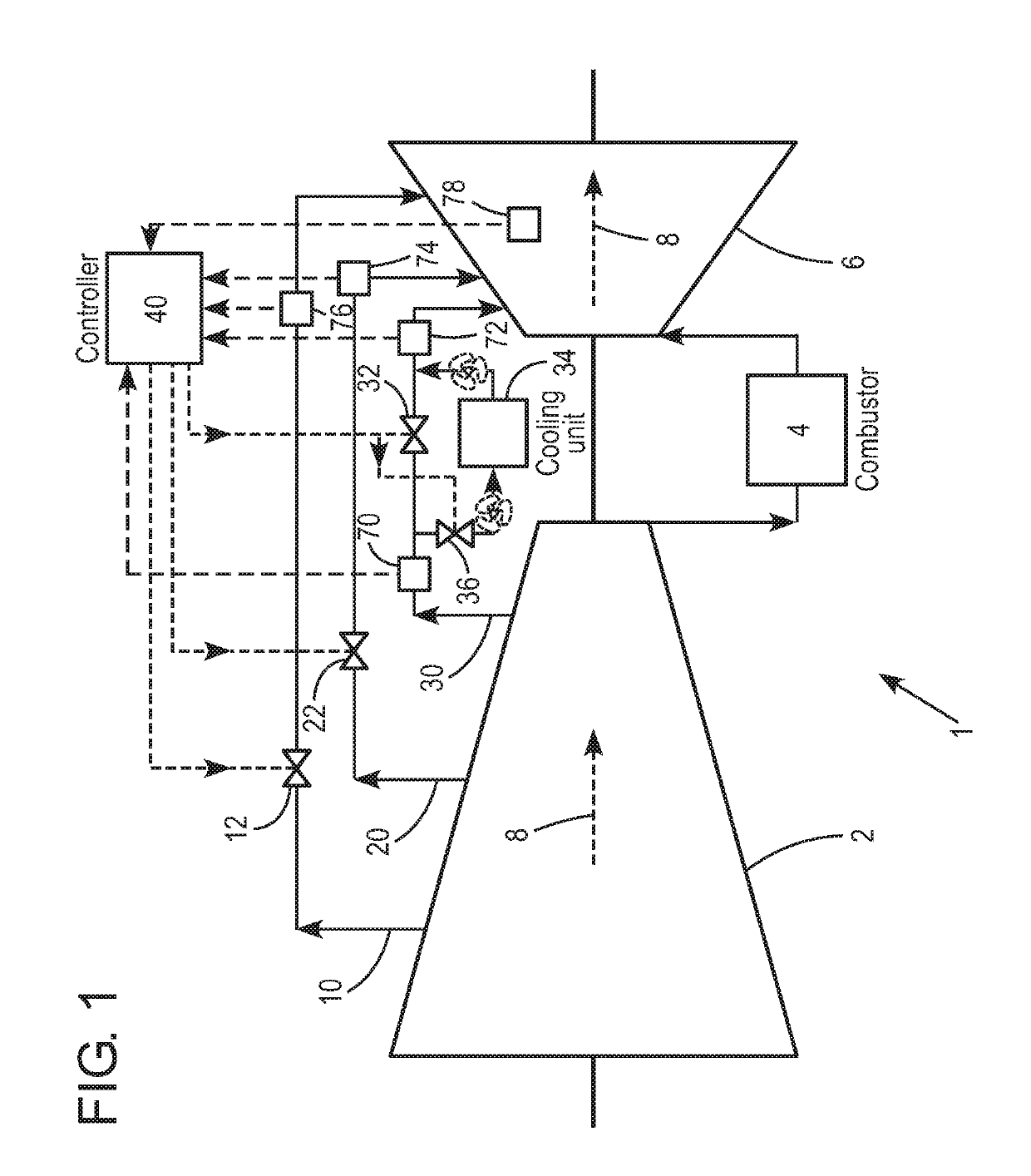
[0018]A gas turbine 1 is described with reference to FIG. 1. The gas turbine 1 comprises a compressor 2, a combustor 4 downstream of the compressor 2 and a turbine 6 downstream of the combustor 4.

[0019]Air flows into the compressor 2 where it is compressed, sent to the combustor 4 and mixed with fuel in the combustor 4. The hot gases resulting from combustion of the air-fuel mixture in the combustor 4 are sent to the turbine 6 and expanded in the turbine 6. Dashed arrows 8 show the general flow direction of air through the compressor 2 and of hot gases through the turbine 6. This fluid flow direction 8 also corresponds to the direction of the axis of the gas turbine 1.

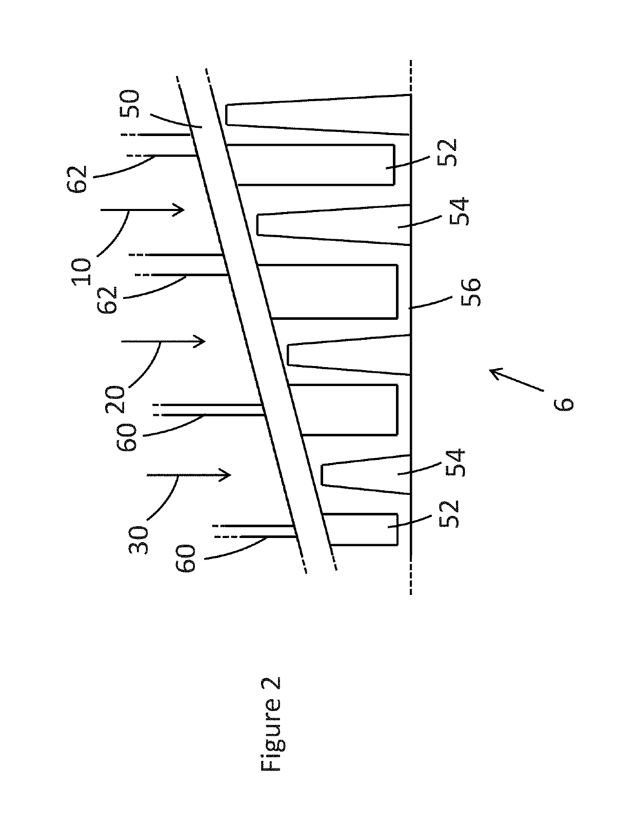
[0020]For cooling, a portion of the air in the compressor is bled off at three locations, resulting in pipes directing first, second and third cooling air flows, namely high-pressure cooling air 30, medium-pressure cooling air 20 and low-pressure cooling air 10 respectively. Each of the pipes has a control valve, namel...


PUM


Abstract

The application describes a method of operating a gas turbine during a cool-down phase. The gas turbine provides a compressor, a combustor downstream of the compressor, and a turbine downstream of the combustor, with the turbine providing a turbine vane carrier. The method includes feeding a flow of cooling air from the compressor to the turbine vane carrier, measuring a temperature of the flow of cooling air and measuring a temperature of the turbine vane carrier. In the method, the flow of cooling air is fed at a first flow rate when the temperature of the turbine vane carrier is lower than the temperature of the cooling air, and the flow of cooling air is fed at a second flow rate when the temperature of the turbine vane carrier is higher than the temperature of the cooling air, wherein the first flow rate is higher than the second flow rate.

Description

TECHNICAL FIELD[0001]The present disclosure relates to methods of operating a gas turbine, and particularly methods of operating a gas turbine during a cool-down phase.BACKGROUND OF THE INVENTION[0002]Systems with rotors and stators such as gas turbines generally require a gap to be left between the rotating part and the stationary part to provide clearance and avoid rubbing. However, providing a gap allows for leakage through the gap. As leakage through such gaps reduces efficiency in gas turbines, there is a general desire to minimise the size of these clearance gaps in gas turbines.[0003]Various factors can play a part in establishing clearance requirements, including the large temperature variations seen in gas turbines. These temperature variations can result in significant amounts of thermal expansion, and this can be further complicated by the use of materials with different coefficients of thermal expansion and by differences in the rate of cooling of different parts.[0004]O...

Claims


Application Information

Patent Timeline
Patent Type & Authority Patents(United States)
IPC IPC(8): F02C7/18F01D11/24F01D21/00F02C3/04F01D25/12F02C9/00F01D21/04F01D21/12
CPCF02C7/18F01D11/24F01D21/00F02C3/04F02C9/00F01D25/12F01D21/12F01D21/04
Inventor ROBSON, CHRISTOPHER MICHAELPATHAK, GAURAVFILKORN, GUENTERRUETER, ANDREASCATALDI, GIOVANNI
Owner ANSALDO ENERGIA SWITZERLAND AG
Learn More